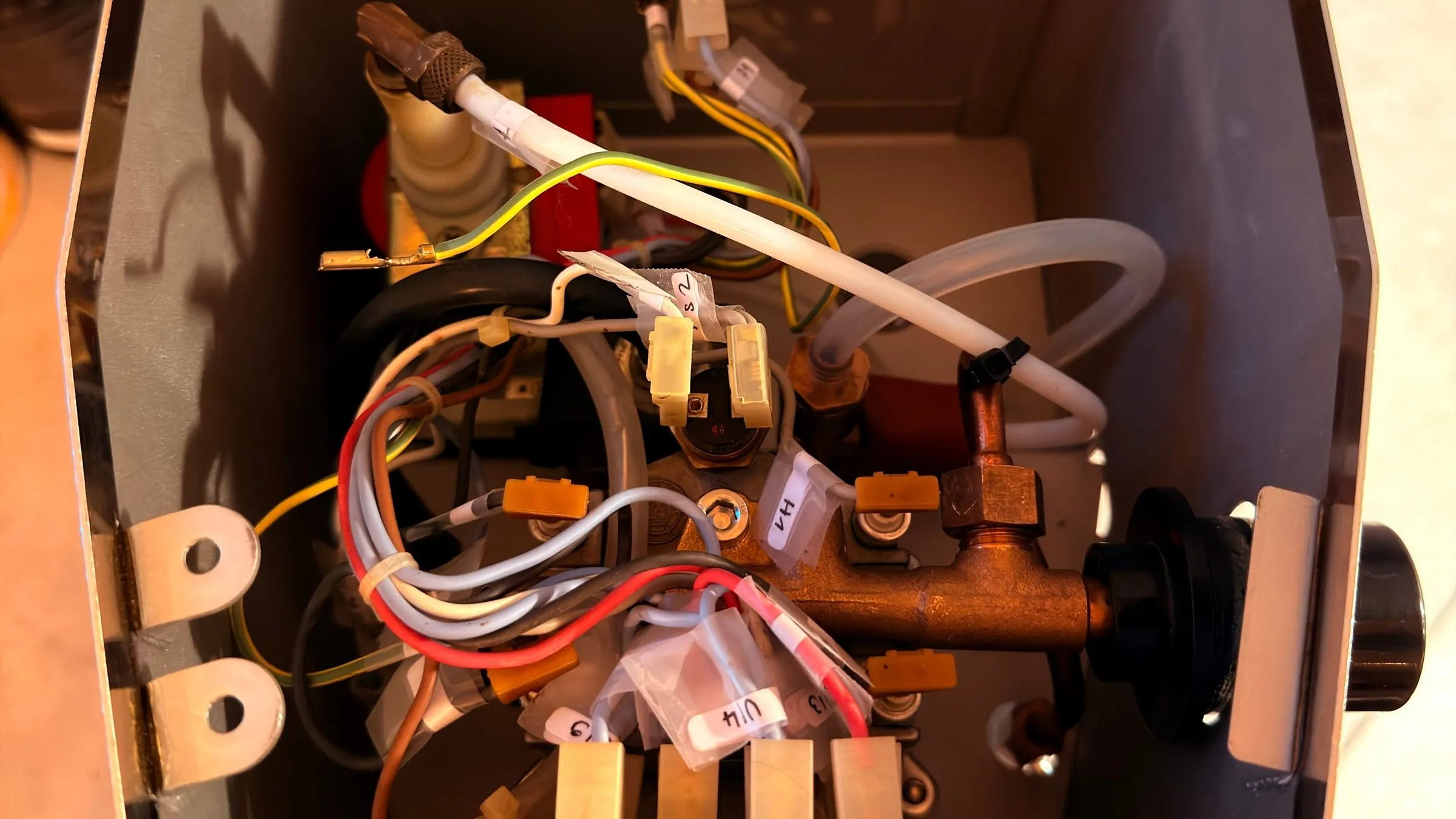
How a 2004 Gaggia Classic works inside, as two sheets of seven panels: the stock machine, and the same machine with a GaggiMate Pro. Each panel is below with its key; the sheets are also printable on two A4 pages each.
This is Part 3 of the series, a reference for the first two: the machine is the one from the restoration (Part 1) and the GaggiMate conversion (Part 2).
Overview
Print version
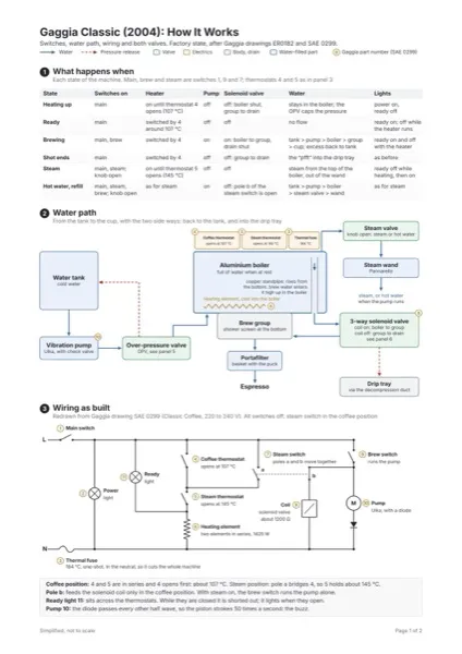 Gaggia Classic (2004): How It WorksDownload
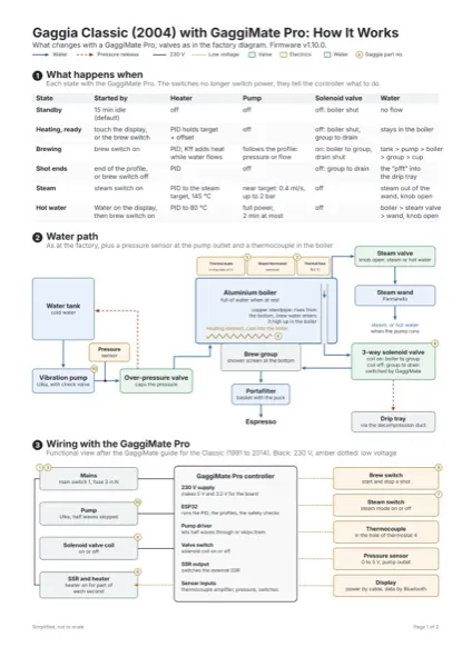 Gaggia Classic (2004) with GaggiMate Pro: How It WorksDownload
Reading the drawings
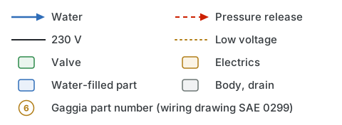
All drawings on this page share one set of colours and symbols. A number in an amber circle is Gaggia's part number and means the same part in every drawing and table.
Stock Classic
Factory state, after Gaggia's parts drawing ER0182 and wiring drawing SAE 0299. Pull the plug before any measurement.
Operating states
Which switches are on in each state of the machine, and what heater, pump, solenoid valve and lights then do. The numbers are the parts in the wiring: main switch 1, brew switch 9, steam switch 7, thermostats 4 and 5.
| State | Switches on | Heater | Pump | Solenoid valve | Lights |
|---|---|---|---|---|---|
| Heating up | main | on until thermostat 4 opens (107 °C) | off | off: boiler shut, group to drain | power on, ready off |
| Ready | main | switched by 4, around 107 °C | off | off | ready on; off while the heater runs |
| Brewing | main, brew | switched by 4 | on | on: boiler to group, drain shut | ready on and off with the heater |
| Shot ends | main | switched by 4 | off | off: group to drain | as before |
| Steam | main, steam; knob open | on until thermostat 5 opens (145 °C) | off | off | ready off while heating, then on |
| Hot water, refill | main, steam, brew; knob open | as for steam | on | off: pole b of the steam switch is open | as for steam |
Water path
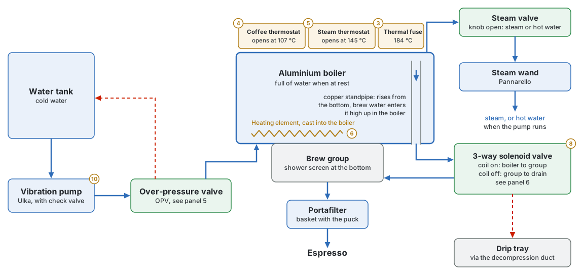
- Brewing: tank, pump, over-pressure valve, boiler, standpipe, solenoid valve, group, puck, cup.
- Heating up: with every valve shut the heated water expands; above its set pressure the over-pressure valve lets the excess back to the tank.
Wiring
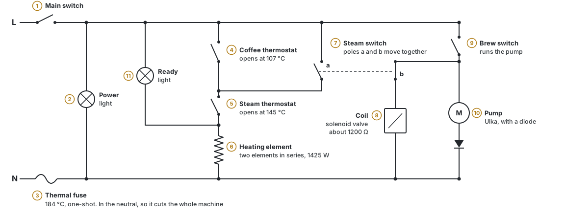
- Coffee position: 4 and 5 are in series and 4 opens first: about 107 °C. Steam position: pole a bridges 4, so 5 holds about 145 °C.
- Pole b feeds the solenoid coil only in the coffee position. With steam on, the brew switch runs the pump alone: hot water from the wand.
- Ready light 11 sits across the thermostats: dark while they are closed, lit when they open. After steaming it stays lit because the boiler is too hot; flush until it goes out, then wait until it comes on.
- Pump 10: the diode passes every other half wave, so the piston strokes 50 times a second: the buzz.
This machine: two elements of about 22 Ω; at the socket the heater delivers about 1150 W, not the 1425 W of the type plate.
Thermostat
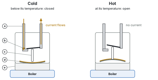
- (a) Terminals: to the wiring.
- (b) Contacts: a spring arm pressed onto a fixed contact.
- (c) Ceramic pin: passes the movement on, does not conduct.
- (d) Bimetal disc: at its temperature it snaps over in one go.
- (e) Brass base: screwed onto the boiler, brings the warmth to the disc.
Closed, current flows to the heater and the ready light stays dark; open, the heater is off and the light comes on. Some degrees cooler the disc snaps back, so the boiler never holds an exact temperature. A cold thermostat reads about 0 Ω.
Over-pressure valve
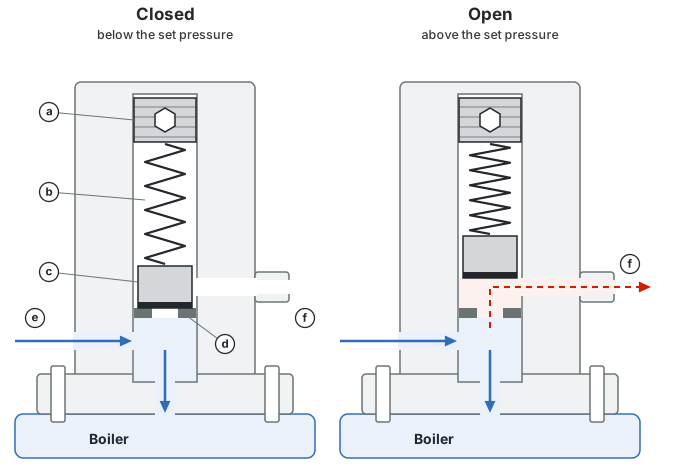
- (a) Adjuster: 5 mm hex; clockwise raises the set pressure.
- (b) Spring: holds the piston on the seat.
- (c) Piston: with a seal underneath.
- (d) Seat: nothing gets past below the set pressure.
- (e) From the pump: under the seat and on into the boiler.
- (f) Back to the tank: opens above the set pressure.
It caps the pump's up to 15 bar and lets out the expansion of the shut boiler. Gaggia publishes no factory setting for the 2004 Classic (the later Classic Pro ships at about 12 bar, the Evo Pro at 9 bar).
This machine: 8.5 bar after the restoration, 12 bar since 18 October 2026.
3-way solenoid valve
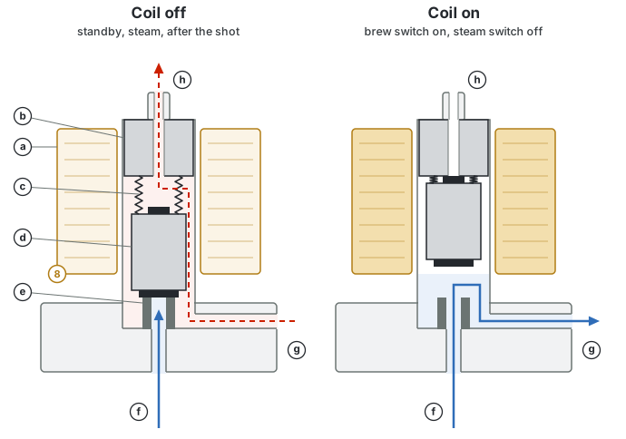
- (a) Coil (8): pulls the plunger up while it is on.
- (b) Fixed core: with the exhaust bore.
- (c) Spring: pushes the plunger down.
- (d) Plunger: a seal at each end.
- (e) Inlet nozzle: its rim is the seat of the lower seal.
- (f) Inlet: from the boiler, through the standpipe.
- (g) Group port: to the brew group.
- (h) Exhaust: to the drip tray.
Coil off, the lower seal shuts the inlet and the group vents: the "pfft". Coil on, the upper seal shuts the exhaust and water flows to the group. A working valve clacks and then hums while the coil is on. With the coil off only the spring holds the lower seal against the boiler pressure; a dirty or worn seal lets boiler water through the valve into the drip tray.
This machine: boiler and water circuit are tight. Only the valve's lower seal does not shut completely, so a little water passes to the drip tray: 8.4 bar in the GaggiMate's pressure test with the valve closed, 13 bar against the blind filter.
Fault finding
| Symptom | Likely cause | How to check | See |
|---|---|---|---|
| No power light, nothing works | Thermal fuse 3 blown (boiler overheated) | Fuse 0 Ω when intact; check cord, switch 1 | Wiring |
| Cold boiler, ready light on | Thermostat 4 or 5 stuck open | Cold thermostats read 0 Ω | Wiring, Thermostat |
| Cold boiler, ready light off | Heating element open | About 22 Ω per element; infinite to the body | Wiring |
| Pump runs, group stays dry | Steam switch on, or solenoid valve stuck | Steam switch off; the coil should click and hum | Wiring, Solenoid valve |
| Pump buzzes, no water | Air in the pump, or no water at the intake | Fill the tank, open the knob, pump until the wand runs | Water path |
| Drip tray fills while heating | Solenoid valve: lower seal does not shut fully | Gaggia's 20-minute test; clean, renew the plunger | Solenoid valve |
| Wet puck, portafilter drips | Solenoid exhaust blocked by scale | No "pfft" after the shot; descale the valve | Solenoid valve |
| Low pressure on a gauge | Over-pressure valve set low, or dirt on its seat | Adjuster clockwise raises it; clean the seat | Over-pressure valve |
| Burnt taste after steaming | Boiler still near 145 °C | Flush until the ready light goes out, then wait for it | Operating states, Wiring |
With a GaggiMate Pro
The GaggiMate Pro replaces both thermostats with a probe and a PID controller, switches the heater through a solid-state relay (SSR), and measures pressure and drives the pump. Valves, pump and boiler stay as at the factory; the switches only tell the controller what to do. Figures are firmware v1.10.0 defaults.
What the conversion changes, part by part
| Function | Factory (2004) | With GaggiMate |
|---|---|---|
| Brew temperature | Thermostat 4 switches the heater at 107 °C | PID holds the set target |
| Steam temperature | Thermostat 5 opens at 145 °C | PID to 145 °C; thermostat 5 removed |
| Switches 7 and 9 | Carry 230 V to pump, valve and heater | Low-voltage inputs to the controller |
| Pump 10 | Full power while switch 9 is on | Power from the profile, set per half wave |
| Solenoid valve 8 | On with switch 9, via pole b of switch 7 | Switched by the controller |
| Pressure | Set by the over-pressure valve alone | Measured; the valve stays the upper limit |
| Overheat safety | Thermal fuse 3 | Thermal fuse 3, kept |
Operating states with GaggiMate
What starts each state now, and what the controller then does with heater, pump and solenoid valve.
| State | Started by | Heater | Pump | Solenoid valve |
|---|---|---|---|---|
| Standby | 15 min without input | off | off | off: boiler shut |
| Heating, ready | touching the display, or the brew switch | PID holds target plus offset | off | off: boiler shut, group to drain |
| Brewing | brew switch on | PID; Kff adds heat while water flows | follows the profile: pressure or flow | on: boiler to group, drain shut |
| Shot ends | end of the profile, or brew switch off | PID | off | off: group to drain |
| Steam | steam switch on; knob open | PID to 145 °C | near the target: 0.4 ml/s, up to 2 bar | off |
| Hot water | Water on the display, then brew switch on; knob open | PID to 80 °C | full power, 2 min at most | off |
Water path with sensor
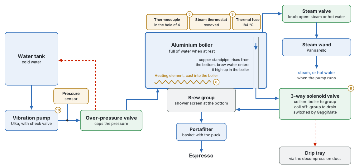
New: a pressure sensor at the pump outlet and a thermocouple in the hole of thermostat 4. The steam thermostat is gone, the thermal fuse stays. With the valve closed the sensor also reads the boiler, so heating alone shows pressure (3.7 bar at 96 °C here).
Wiring around the controller
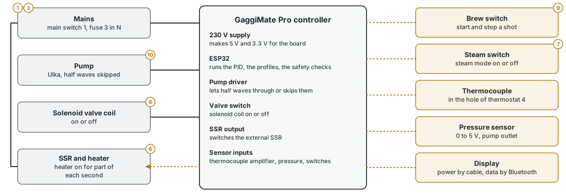
Pump and solenoid coil hang on the controller; the heater runs through the external SSR. Brew and steam switch are low-voltage inputs. The display gets power by cable and data by Bluetooth.
Temperature loop
A thermostat is a switch: full power until the boiler is hot, then nothing, so the temperature swings by several degrees. The GaggiMate measures the boiler several times a second and gives the heater only as much power as it needs to reach the target and stay there.
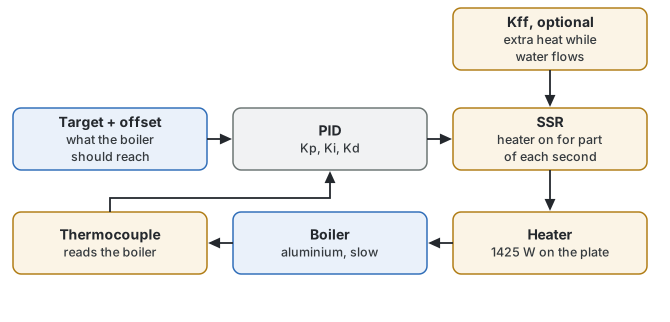
- Target: the brew temperature set on the display.
- Offset: the boiler wall runs hotter than the water at the puck, so the controller holds target plus offset (Classic preset 8 °C) and the display subtracts it again.
- PID: reacts to the gap (Kp), to its history (Ki) and to its trend (Kd); the next section shows what each one does.
- SSR: a solid-state relay; it switches the heater on for 0 to 1000 ms of every second.
- Kff: adds heat in step with the pump flow while the valve is open; off once the boiler is 1 °C above target.
- Steam and hot water: the same loop with other targets, 145 °C and 80 °C by default.
Tuning: Kp, Ki, Kd and Kff
Every second the controller decides how long the heater may run in the next second. It adds up four parts, each answering one question about the boiler, and each K says how much its answer counts:
- Kp, the present: how far below the target is the boiler now?
- Ki, the past: for how long has it been off?
- Kd, the trend: how fast is the gap growing or closing?
- Kff, ahead: how much cold water is flowing in right now?
The autotune measures the boiler and sets Kp, Ki and Kd; Kff is optional. The charts show what turning one value up or down does during a shot, simulated, so only the shapes matter: top the boiler temperature (dotted: the target), bottom the heater power.

Kp: how far off now
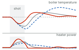
The bigger the gap, the more heat, like pressing the accelerator harder the further a car is below the speed it should go. Higher: smaller dip, but the temperature swings. Lower: deep dip, slow rise.
Ki: for how long
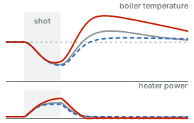
Adds up every gap so far. A gap that lasts keeps this part growing until the gap is gone, which removes a small offset that Kp alone leaves. Higher: overshoots, and stays too hot for long. Lower: calm, but slow to settle.
Kd: how fast it changes
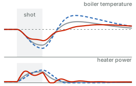
Watches how fast the gap changes and brakes before the target is reached, like easing off the accelerator as the car nears its speed. Higher: calmer temperature, jumpy heater power. Lower: more overshoot.
Kff: what flows in
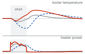
Does not wait for the boiler to cool: while the pump runs it adds the heat the incoming cold water will need. Higher: hotter during the shot. Lower or 0: the temperature dips during the shot.
More details: the numbers, the autotune and this machine
The sum. The four parts give the heater time for the next second in milliseconds, between 0 and 1000. Kp is that time per degree of gap: with Kp 36.5, a boiler 1 °C below target gets about 36 ms of heat per second, one 10 °C below about 365 ms. Ki multiplies the gaps added up over time, Kd the change of the gap per second, Kff the heat the measured pump flow carries away.
The autotune heats the boiler for a set time and measures how fast it warms and how long it takes to react, then computes Kp, Ki and Kd from that. On firmware v1.9.0 and later it sits in the web interface under Settings, Calibration: start it with the boiler below 50 °C, test duration 120 s by default. It asks for the heater wattage and suggests 1360 W; enter what the heater really delivers. The firmware also derives Kff from it: 1000 divided by the wattage (1360 W gives 0.735).
This machine. At the socket the heater delivers about 1150 W, not the 1425 W of the type plate (Kff from that would be about 0.87). Three autotune runs between 31 October and 9 November 2026 measured heating rates from 0.70 to 1.8 °C/s, so the results scatter; a fourth hit the lowest values the firmware allows (Kp 20, Kd 50) and is unusable. The recipe for this machine stays with the values of the first run, Kp 36.526, Ki 0.450, Kd 389.444, and Kff 0: with Kff on, a shot started more than 1 °C above target lost 4 to 5 °C, one started closer gained 2 to 7 °C. The setup assistant of firmware v1.10.0 sets its own Classic preset (58.397, 1.027, 249.055); check the values after an update.
Pressure loop
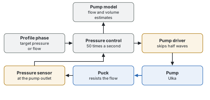
- Pressure target: the controller sets the pump power so the sensor reading follows the profile.
- Flow target: the controller holds the flow its pump model predicts, with a pressure limit.
- Pump driver: lets each half wave of the mains through to the Ulka, or skips it.
- Over-pressure valve: still caps the pressure; set it above the highest pressure of your profiles.
- Estimates: flow and volume come from the pump model, not a flow meter; without a scale they are approximate.
- Phases: each phase ends after a time, a pressure, a flow or a volume, whichever the profile sets. A weight target counts only with a Bluetooth scale.
Fault finding with GaggiMate
| Symptom | Likely cause | What to do |
|---|---|---|
| Display: control inhibited | Display and controller on different firmware | Update the controller too |
| Heater and pump stop (error 5) | No sign of life from the display for 20 s | Check the link; restart both |
| Pressure stuck near 14.5 bar | Black wire of the pressure sensor loose | Reseat the sensor wiring |
| Pressure near 16 bar | Red and black sensor wires swapped | Swap them back |
| Temperature climbs during the shot | Kff on, shot started near the target | Kff 0, or start hotter |
| Autotune fails or hangs | Not started from a cold machine | Start it cold, as the guide says |
| Pressure test under 10 bar | Solenoid valve does not shut fully with the coil off | Water at the exhaust? Clean the valve |
| No heat, SSR LED dark | SSR signal cable, or no heat request | Check the cable while heating up |
Sources
- Gaggia: parts diagram ER0182; wiring diagram SAE 0299 (230 V) and 17800009 (120 V), both listed by Whole Latte Love; the Classic manuals.
- GaggiMate: installation guide for the Classic (1991 to 2014), troubleshooting, and the firmware source at v1.10.0.