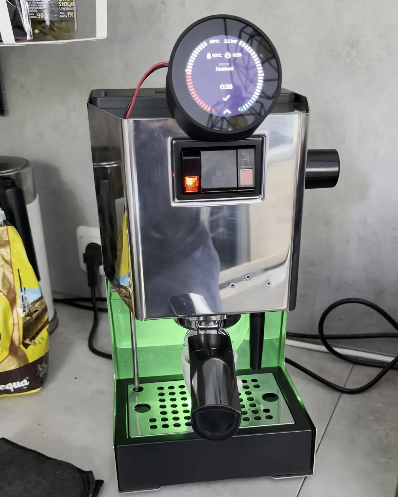
Part 1 ended with a restored Gaggia Classic that made good espresso and could not make the same espresso twice: a 2004 bimetal thermostat swings several degrees around its set point. This part replaces both thermostats with a GaggiMate Pro, an open-source ESP32 controller with a PID loop, a round touch display and, in the Pro version, a pressure sensor and pump control. The installation took one afternoon. The days after it taught me more about the firmware than the installation did about the hardware.
This is Part 2 of the series. Part 1, the restoration from the EUR 200 find to the first shot, is where the machine, the 8.5 bar and the blind filter used below come from. A third part will follow once the machine has been polished as a system: profiles, cable management, a better place for the electronics inside the housing.
| Item | Detail |
|---|---|
| Machine | Gaggia Classic, built 05/2004, restored in Part 1 |
| Controller | GaggiMate Pro, board Rev 1.1, firmware v1.8.1, with pressure sensor and pump control |
| Installed | 22 September 2026; first shots on the 23rd, self-tests on the 24th |
| Kit | The GaggiMate Pro kit for the Gaggia Classic, listed from about EUR 213 in the GaggiMate shop at the time of writing |
| Plan | Remove both thermostats, fit the probe, the relay and the sensor, leave the over-pressure valve at 8.5 bar for now, then test the machine with its own sensor |
The project at a glance
A GaggiMate installation on a 1991 to 2014 Classic is a wiring job, not a mechanical one: the thermostats come off, a temperature probe goes into one of their threads, a solid-state relay takes over the heater, the switches become buttons, and on the Pro a T-piece with a pressure sensor goes into the line between pump and boiler. The documentation covers the installation well. What this post adds is the afternoon of small decisions on one particular machine, and what I learned afterwards about how a profile actually runs. These are the steps in the order they happened; each row links to its section.
| Step | What it involved | Rough effort |
|---|---|---|
| Before the conversion | ||
| 1.The kit and the plan | What a GaggiMate is, what is in the Pro kit, the guide on paper, the over-pressure valve question · 1 image | An hour with the guide |
| 2.Labels by the wiring sheet | Every connector relabelled with the names the GaggiMate wiring sheet uses · 2 images | Twenty minutes |
| The installation | ||
| 3.Thermostats out, probe in | A thermostat that crumbled, what is inside one, the boiler out for the M4 probe, as the guide says · 4 images | Three quarters of an hour |
| 4.Relay, board and switches | The heater through the relay, the switches turned into buttons, the pump on the board · 2 images | About an hour |
| 5.The pressure sensor and its T-piece | The elbow that has to come off first, the hose that must hold no air · 2 images | Forty minutes |
| 6.First power-up | A boot screen, a brew screen, and 14.1 bar with the pump standing still · 3 images | A quarter of an hour |
| Commissioning | ||
| 7.The 14.1 bar that was a wiring fault | One black wire one terminal too far to the left · 3 images | Half an hour |
| 8.Wi-Fi, PID values and the offset | The access point, the starting values for a Classic, what the offset does in both directions · 0 images | Twenty minutes |
| First shots and what the firmware does | ||
| 9.Two shots: 43.3 g and 36.3 g | The stock profile, 8.5 bar flat on the display, the same grind and two seconds less · 4 images, 1 clip | Twenty minutes |
| 10.What "stop at 36 g" means without a scale | A weight target that is a stopwatch, and how the Pro estimates the yield from the pressure curve · 0 images | An hour of reading |
| The self-test | ||
| 11.A self-test profile for the machine | Six phases against the blind filter, rectangles on the display, a crash in the core dump · 3 images, 1 clip | Half an hour |
| 12.The pressure sensor as a leak detector | 7 bar held without the pump, a jet from the drain pipe when the valve closes · 2 images, 1 clip | Twenty minutes |
| The quick-start guide | ||
| 13.Two pages for the kitchen drawer | Setup on page 1, daily use on page 2, German and English, with the self-test profile to download · 2 images | An evening |
The hours are estimates from the timestamps of my photos, and they count my own time: the installation itself was one afternoon of about three hours, and steps 7 to 12 add up to about three more across the two days after it, two of them at the machine and one reading. Steps 10 and 13 were co-work with Claude, which read the firmware source and drafted the guide; the hours in the table are the ones I spent on them. The kit was the only purchase; its price is in the table above.
What you need: parts
- The GaggiMate Pro kit for the Gaggia Classic 1991 to 2014: board with power supply in a printed housing, round display with bezel and holder, solid-state relay, M4 temperature probe, pressure sensor with T-piece, elbow, PTFE hose and fittings, pre-made cable sets
- Thermal paste for the probe: optional according to GaggiMate; an old syringe is fine as long as it stirs homogeneous
- A blind filter for the self-test, the same one as for backflushing
What you need: tools
- The Part 1 toolkit: the long 5 mm hex key for the boiler screws, 14 and 17 mm spanners for the fittings
- Tape and a pen for the labels, and the wiring sheet printed
- A wire stripper: the board's push-in terminals take 11 mm of bare strand, not tinned
- A syringe to fill the sensor hose
- A phone for the photos: they found the wiring fault the next morning
Before the conversion
1.The kit and the plan
The GaggiMate is what a PID kit for a Classic has become in 2026: not a box with a temperature readout but a small computer. An ESP32 board with its own power supply sits in a printed housing inside the machine, switches the heater through a solid-state relay, holds the temperature with a PID loop and, on the Pro, drives the pump and reads the pressure. A round touch display with its own ESP32-S3 goes on the housing and runs the web interface, and brewing happens by profile: phases with a valve state, a pump setting, a duration and targets. The Pro version, which is what I bought, adds a pressure sensor in the line between pump and boiler and dims the pump, so a profile can ask for 3 bar of preinfusion and a decline to 5.5 bar instead of a switch that is either on or off.
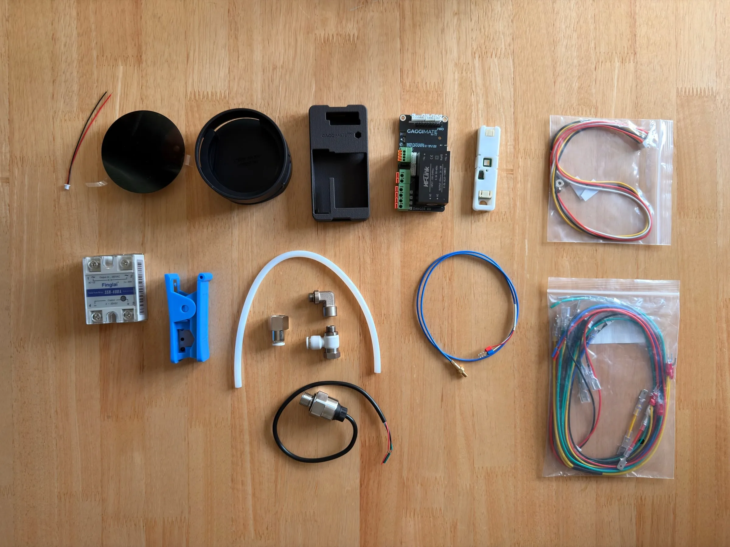
Two things to know before ordering. The documentation has a separate installation guide for the Gaggia Classic of 1991 to 2014, which is this machine: its wiring is not the Classic Pro's, and the guide has its own wiring sheet with its own connector names. And the kit is ordered per machine: on the shop page the choice sets the probe thread, M4 for the Classic, and the variant for this machine is listed as the Gaggia Classic of 1992 to 2012, where the documentation says 1991 to 2014 for the same model. It fitted my 2004 Classic. I built the guide and its wiring sheet into a print PDF from the documentation's source files, 20 pages and 101 photos, and had it on the table next to the machine. Reading it on paper before the first screw comes out, and again whenever a step is unclear, is the cheapest hour of the whole project.
What about the over-pressure valve?
Part 1 left the over-pressure valve at 8.5 bar on the portafilter gauge, as found. GaggiMate gives no target for it: the guide, the firmware repository and the shop pages say nothing about the valve. The logic is simple, though. The valve caps the pressure from above, and the controller can only throttle the pump, never push past the valve. So the valve must sit at least as high as the highest pressure any profile asks for, and a profile that asks for more than the valve allows will simply never get there. For now it is still at 8.5 bar, and my first own profile below peaks at 7.5 bar, deliberately underneath it. Whether to raise the valve so that profiles up to 9 bar and a little beyond become possible is an open question for Part 3; the 15 turns from Part 1 make the setting easy to change and easy to put back.
2.Labels by the wiring sheet
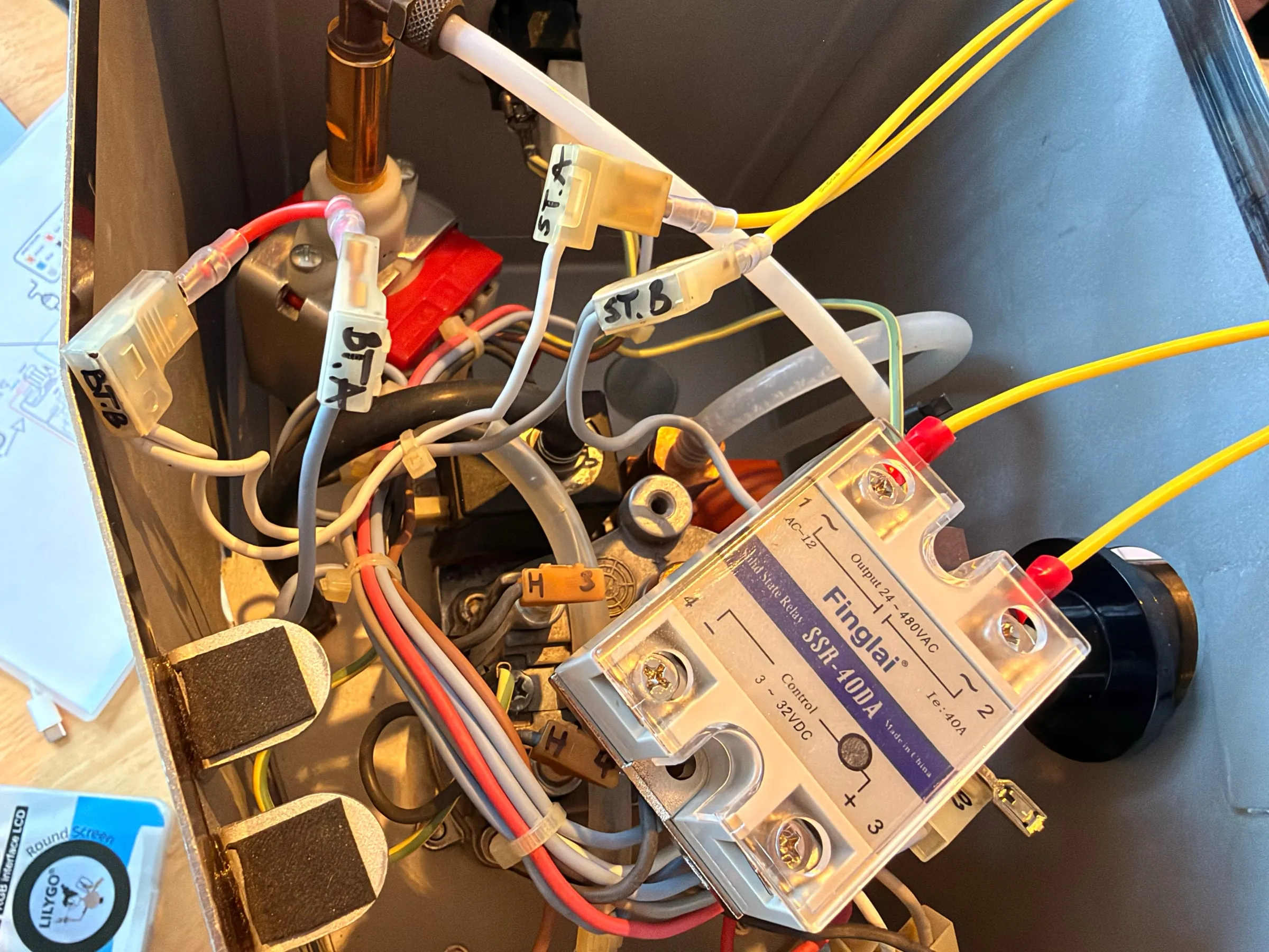
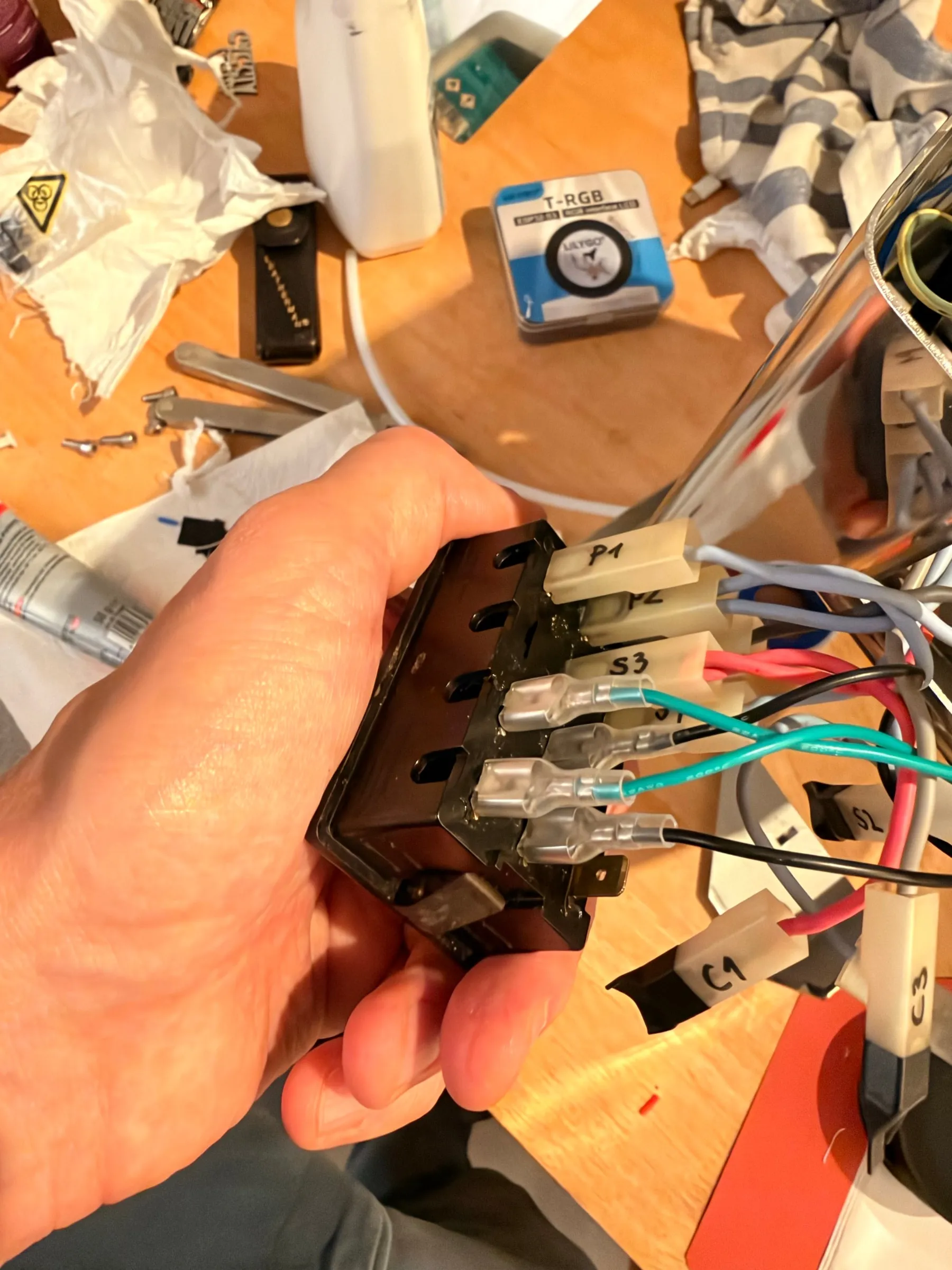
Part 1 had labelled every cable with my own names, H1 to H4 for the heater, PU1 and PU2 for the pump. The GaggiMate wiring sheet uses its own, and the installation is easier if the machine speaks the same language as the paper. So on the afternoon of 22 September every connector got a new tape flag: BT.A and BT.B at the brew thermostat, ST.A and ST.B at the steam thermostat, PMP.A and PMP.B at the pump, C.1 to C.3 at the brew switch, S.1 to S.4 at the steam switch, P.1 to P.3 at the power switch, and H1 to H4 stayed at the boiler.
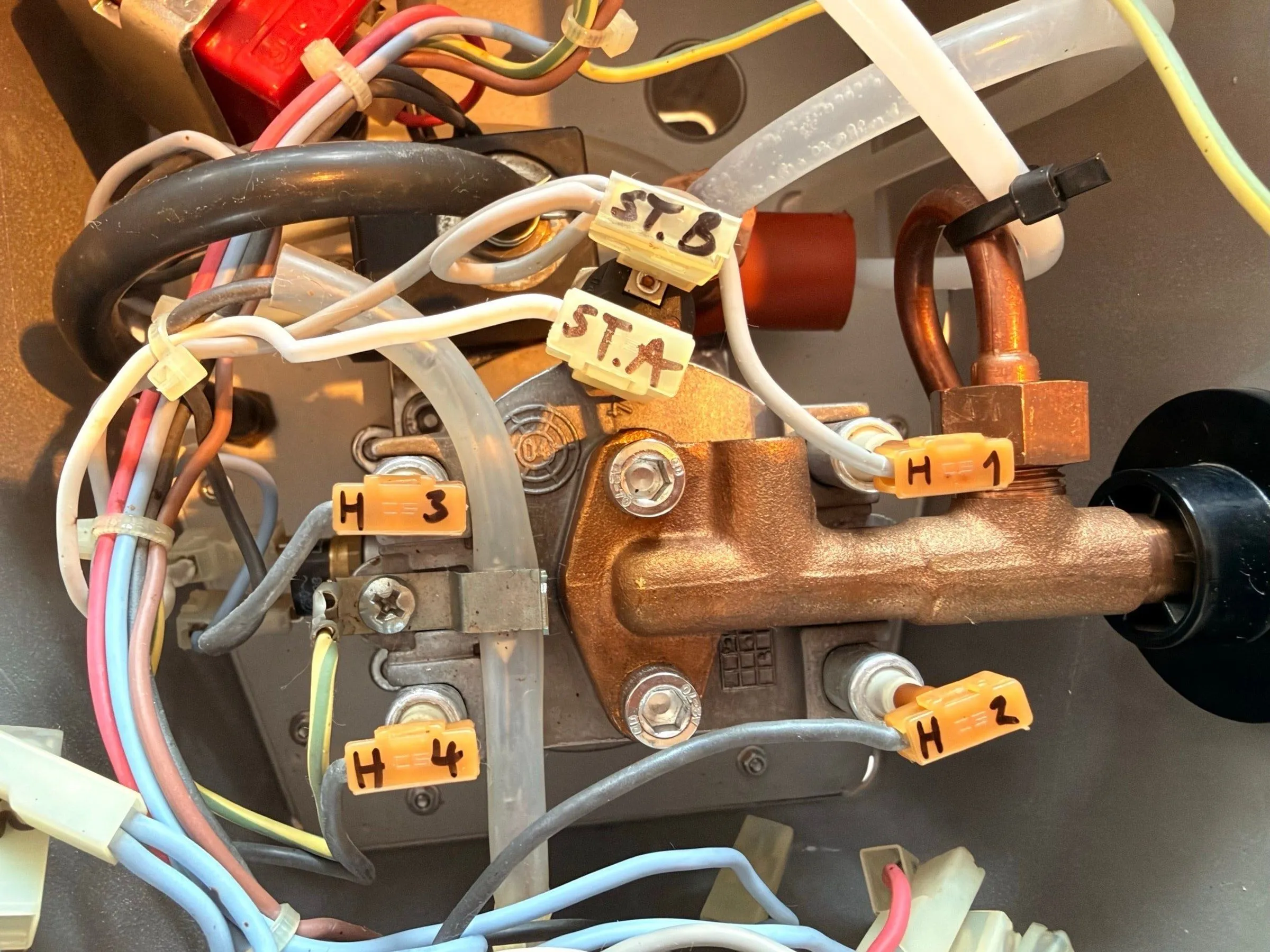
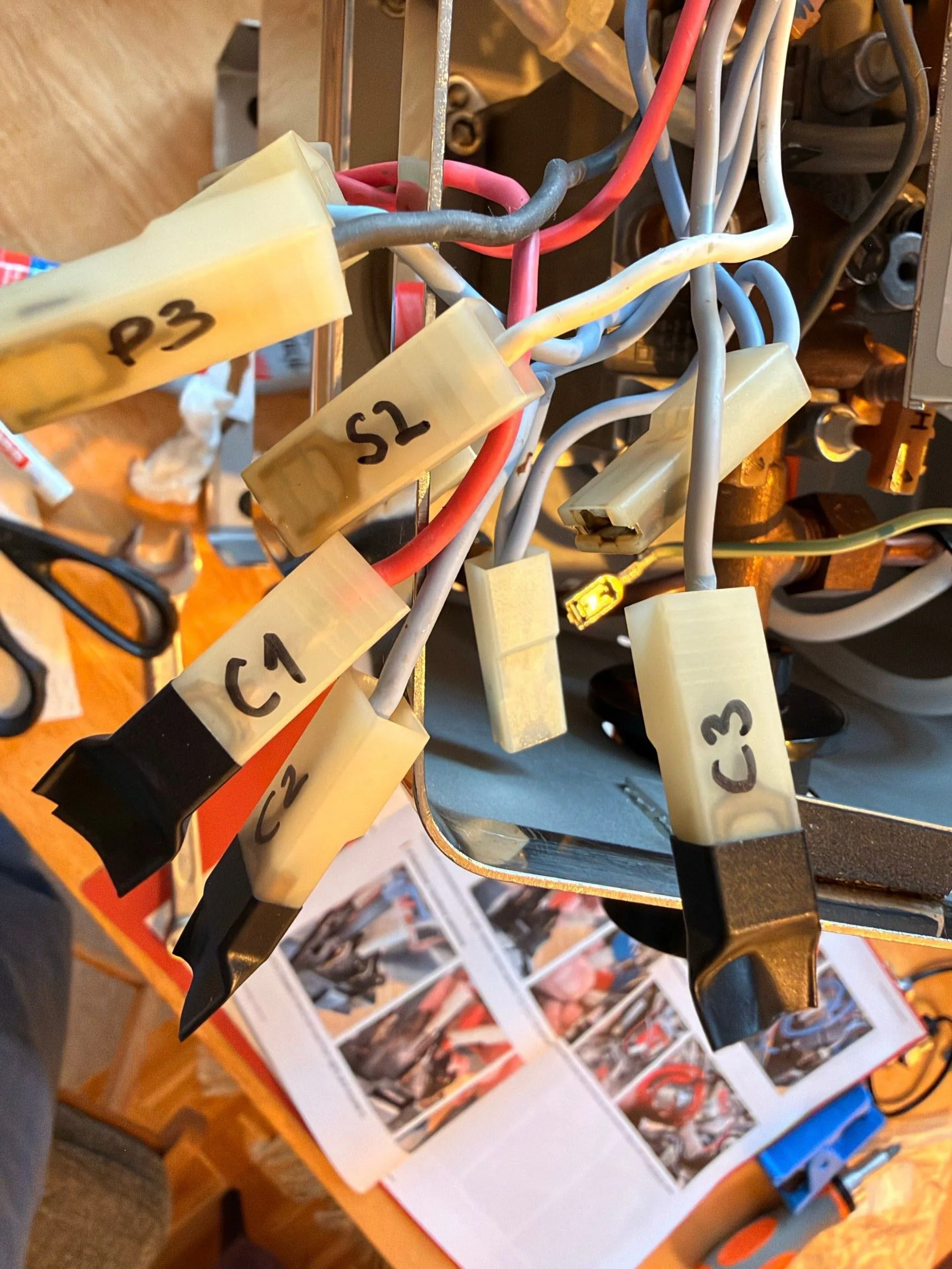
While the housing was off, the front got one more polishing pass, because the result from Part 1 had not fully satisfied me. For that the Gaggia badge had to come off, and that cost two of its legs. I would like it to go back on with magnets, so that it comes off without bending next time, but the stainless housing is not magnetic, so that needs a counterpart behind the panel first; a job for the third part.
The installation
3.Thermostats out, probe in
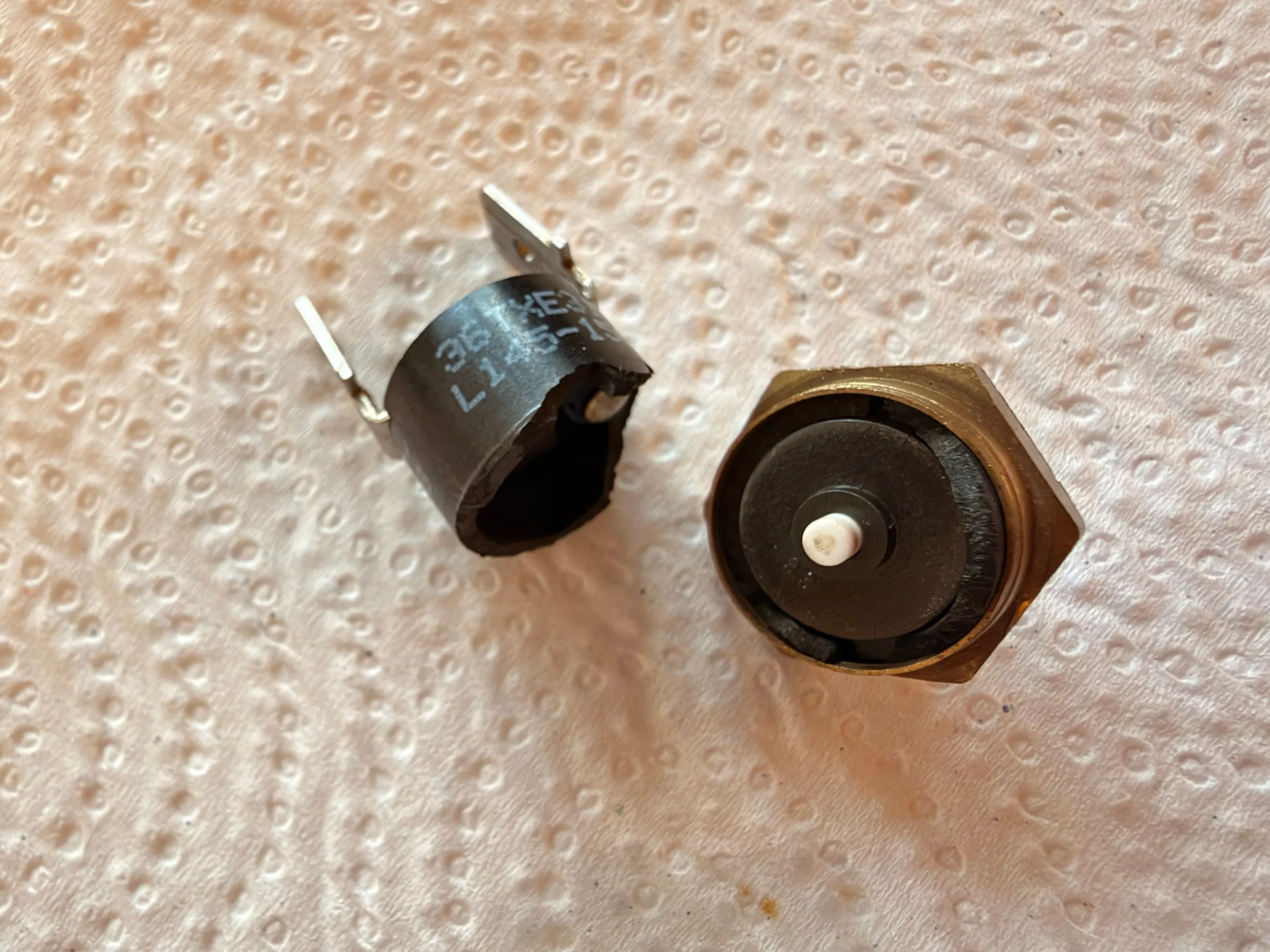
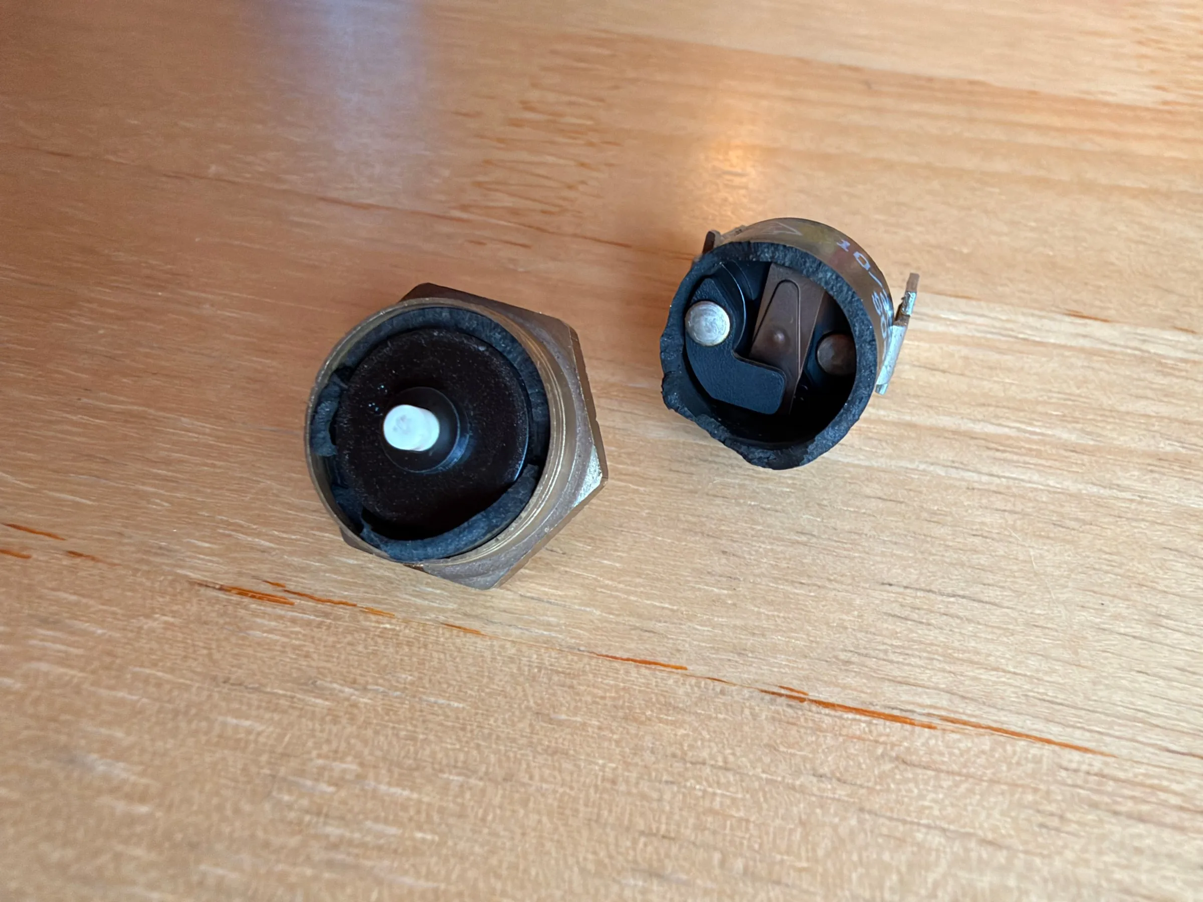
GaggiMate replaces both thermostats: the brew thermostat at 107 °C and the steam thermostat at 145 °C. The brew thermostat came off cleanly. The steam thermostat did not: its plastic body crumbled as the spanner took hold. Not a wrong turn, just twenty years of heat cycles in a plastic that had become brittle. For the conversion it does not matter, the part is retired anyway. A replacement, the 145 °C contact thermostat with the M4 thread, costs under ten euros, and one will go in the drawer so that the machine can go back to stock one day.
What is inside a bimetal thermostat
The broken part answered a question I had never asked. In the brass base sits a bimetal snap disc; above it a ceramic pin. The disc snaps over at its temperature, the pin carries that movement to the contacts in the plastic cap and insulates them from the hot brass at the same time. The pin is the messenger, not the part that expands. That is why a thermostat of this kind switches with a click and swings several degrees: the disc has to travel past its snap point in both directions.
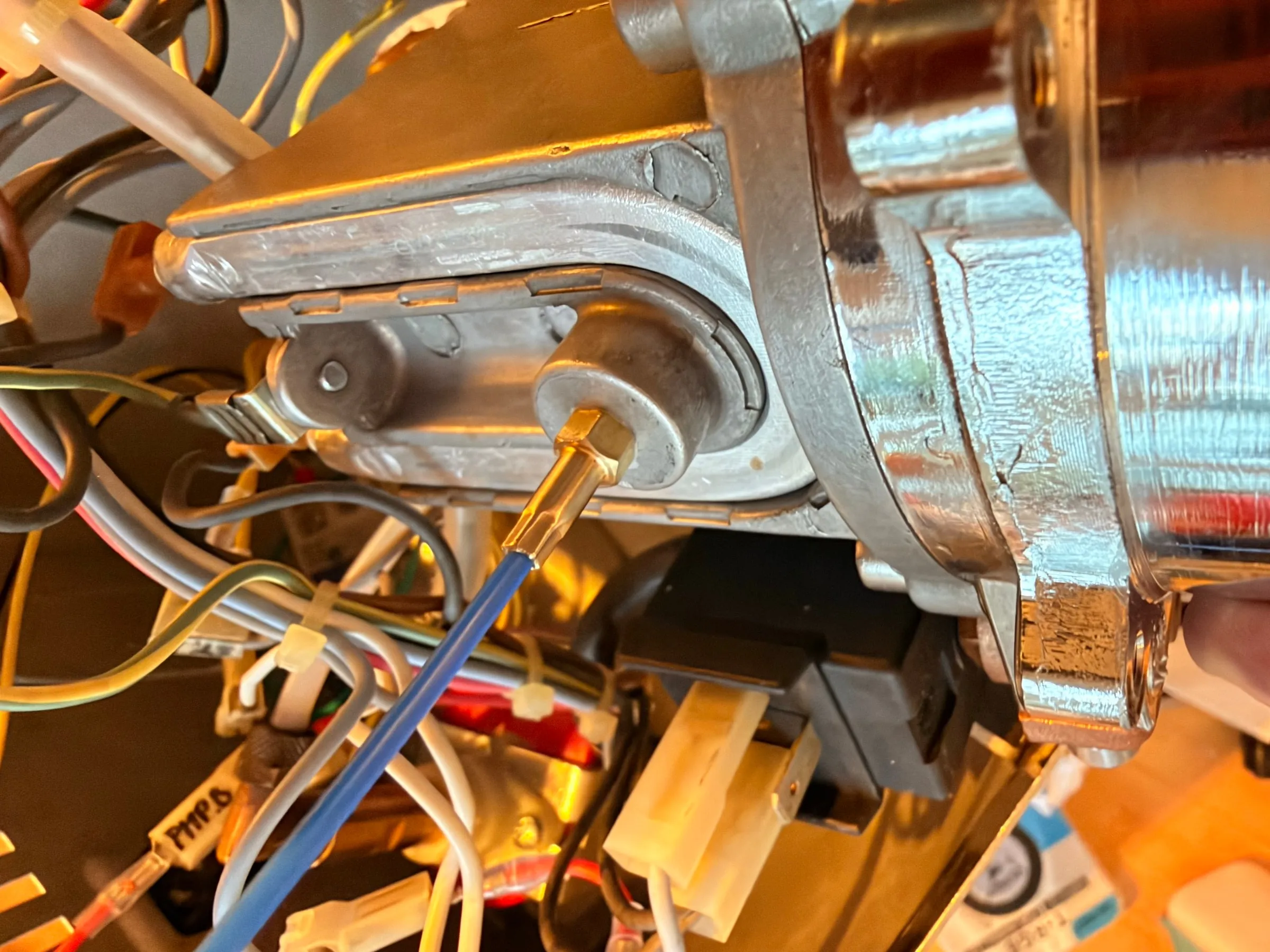
The probe is an M4 sensor on a cable that screws into the thread the brew thermostat left behind, boiler side. The guide says to take the boiler out of the housing for this. I hoped to skip that, because everything else in the conversion can be done with the boiler in place, and learned why the guide says it: with the boiler in the housing there is no clean way to get the probe with its cable onto the thread, and cross-threading an M4 in aluminium is not a risk worth taking. So the boiler came out, for this one step, and the probe went in on the bench: a little thermal paste, screwed in gently, the cable turned with every turn so that it does not twist.
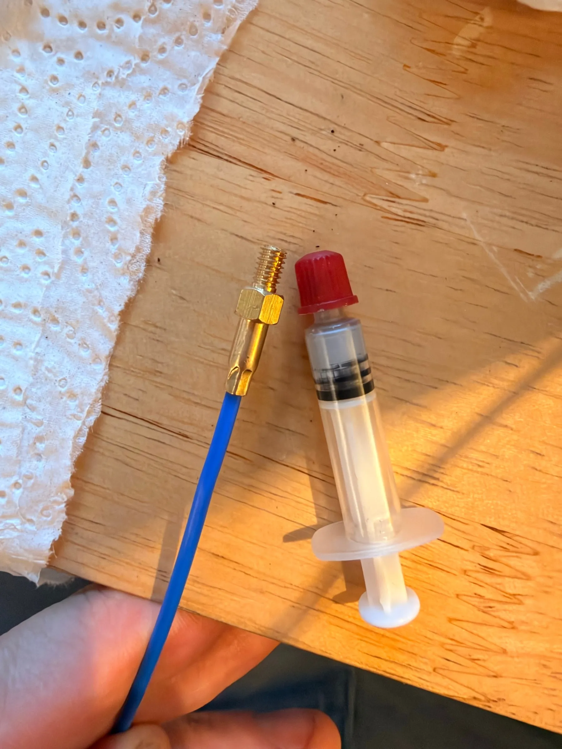
Thermal paste is optional according to GaggiMate. The syringe I had was old, but still fluid and homogeneous after stirring, which is the test that matters; separated paste stays in the drawer.
4.Relay, board and switches
The wiring follows the sheet, and the sheet is worth following to the letter. The two thermostat positions become the relay: BT.A and BT.B are joined with the red bridge cable, so the heater no longer has a thermostat in its path, and ST.A and ST.B go to the solid-state relay through the yellow cables, so the relay now is the thermostat. The relay itself is a Finglai SSR-40DA on the frame, with an LED that lights whenever the heater is on, which turns out to be a useful thing to watch during the first heat-up.
The switches change meaning. The power switch stays what it was, mains on and off, for everything including the GaggiMate. The brew switch loses its mains job: C.1 to C.3 are disconnected and insulated, and C.1 and C.2 now go to the board as a button, so flipping the switch starts a shot. The steam switch is treated the same way, S.2 disconnected, S.1 extended, S.1 and S.2 a button for steam mode. The pump moves from the switch to the board, PMP.A and PMP.B, because the board dims it. And the ready lamp keeps lighting but means nothing any more; the temperature on the display is what counts.
5.The pressure sensor and its T-piece
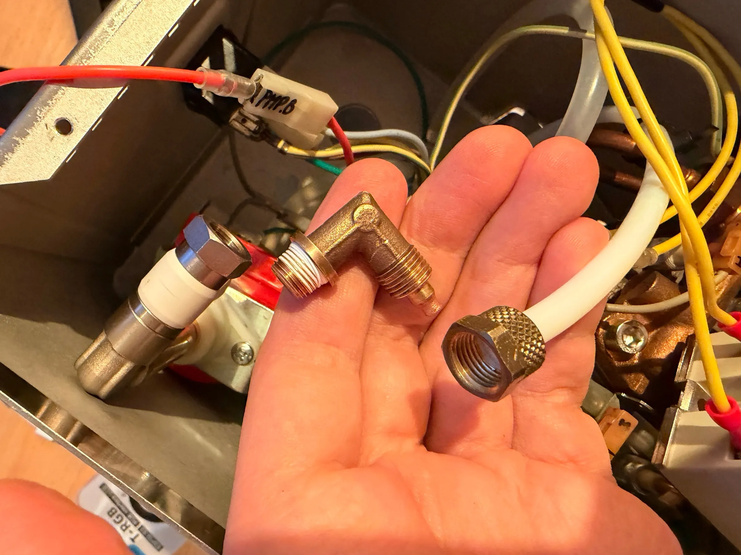
The Pro's pressure sensor sits on a short piece of PTFE hose at a T-piece in the line between pump and boiler. The guide has a section on it, "New plumbing", and its text is exact: loosen the nut on the pump fitting, pull the hose, unscrew the fitting, then the 90-degree elbow from the kit onto the pump, the white T-piece onto that, and last the original fitting onto the end of the T-piece, hose and nut back on. I missed the third step on my first read: going by the pictures, I took the original elbow to stay on the pump, and it was the text that set me straight. The original elbow comes completely off and goes back on at the very end.
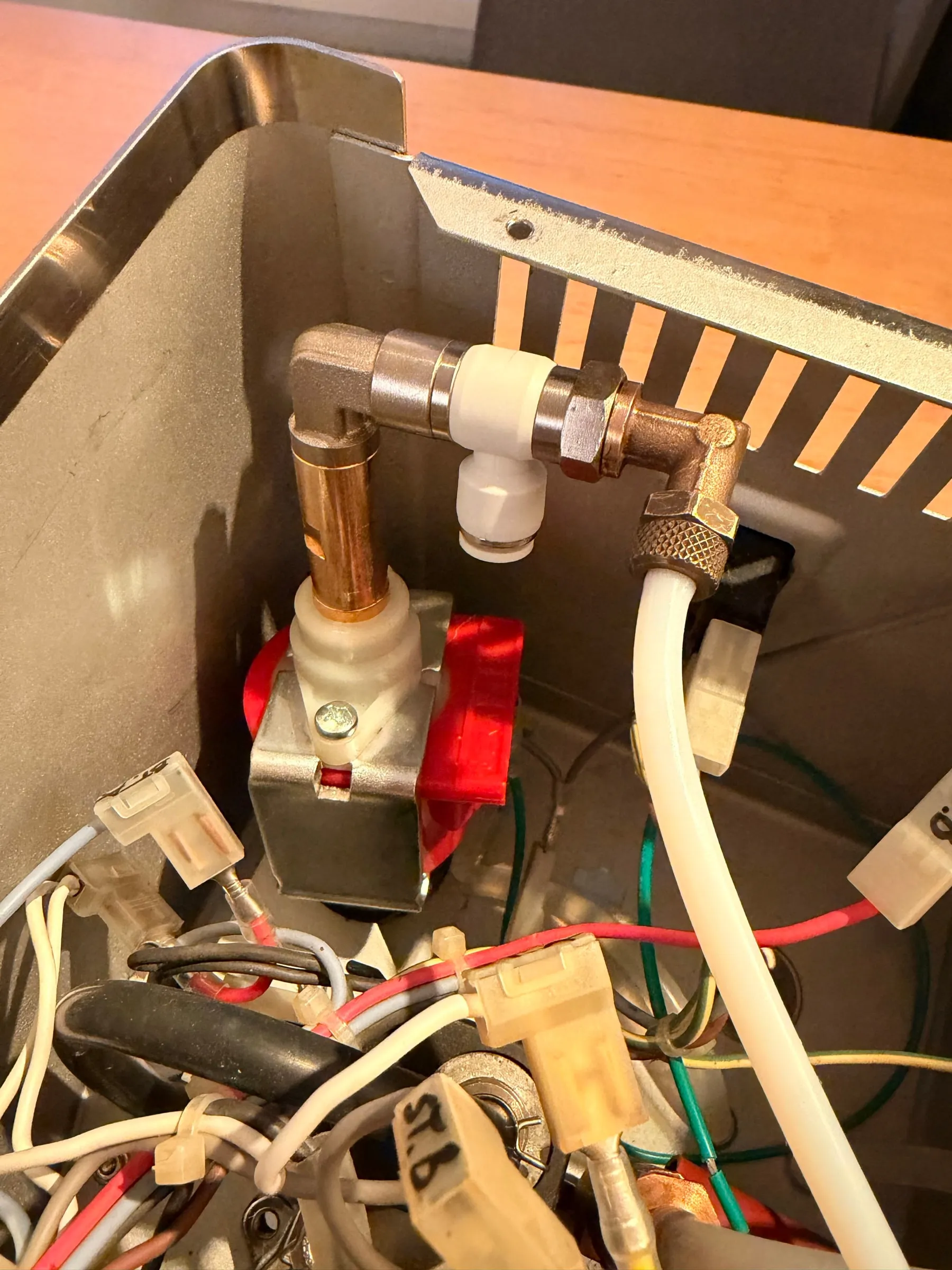
The second job of this step is to fill the sensor hose without air, as the guide says, with a syringe. Air in the sensor hose would make the reading spongy; none may stay in.
6.First power-up
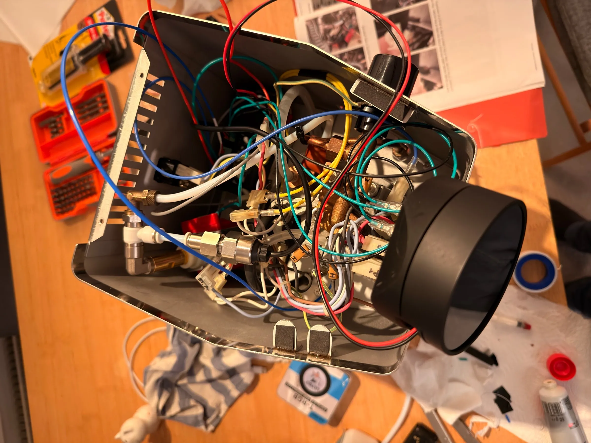
Around 20:00 everything was connected: the display on its holder, the board in its housing, the wires routed as well as a first attempt routes them. The housing stayed open, because the first minutes of a new controller are minutes you want to watch.
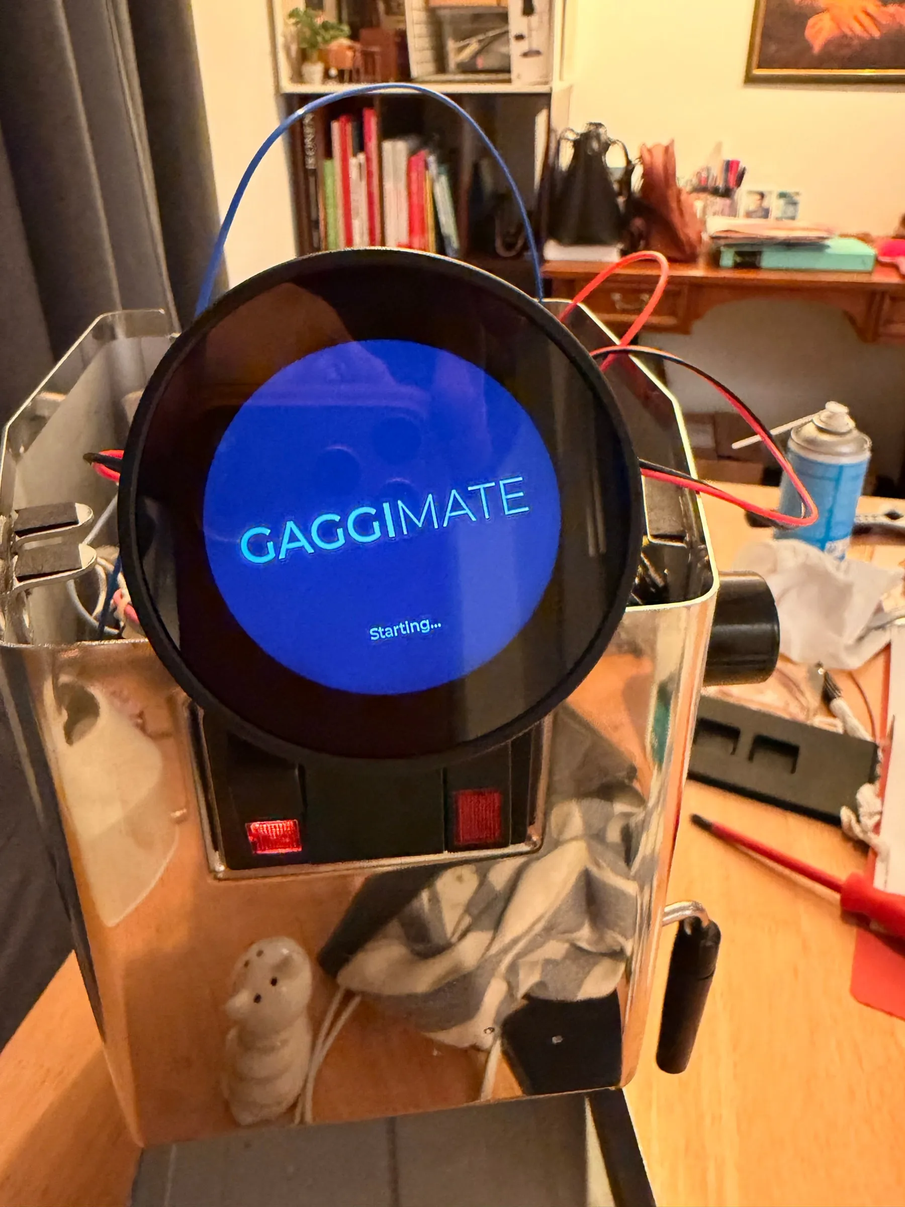
At 20:07 the display booted: "GAGGIMATE, Starting", and shortly after the brew screen with the profile "Default". That was all for the evening, no heating, no shot, no further tests. The screen showed a number that could not be right: 28 °C, plausible for a cold boiler, and 14.1 bar with the pump standing still.
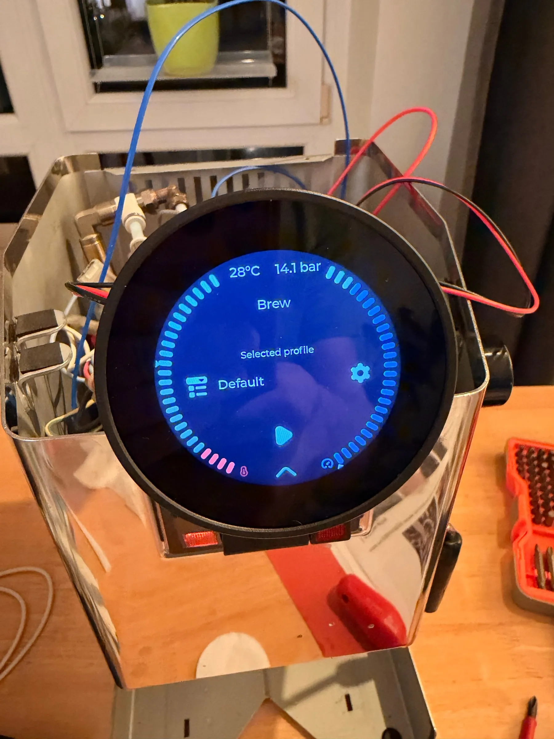
The troubleshooting page lists exactly this: a pressure reading stuck around 14.5 bar means the sensor's black wire is not making contact; a reading of 16 bar means red and black are swapped at the board. So the open point for the next morning was written down before the plug came out: check the sensor wiring before the first heat-up.
Commissioning
7.The 14.1 bar that was a wiring fault
The photos I had taken of the board the evening before settled it before the housing was even open. The pressure sensor has three wires, red, green-turquoise and black, and the board's terminal row for it is labelled 5V, Sig, Sig2, GND. The black wire sat on Sig2. With three wires, Sig2 is the one that stays empty, and an empty terminal at the edge of the row is the wrong picture; the empty one sits in the middle. Red to 5V, the signal wire to Sig, black to GND.
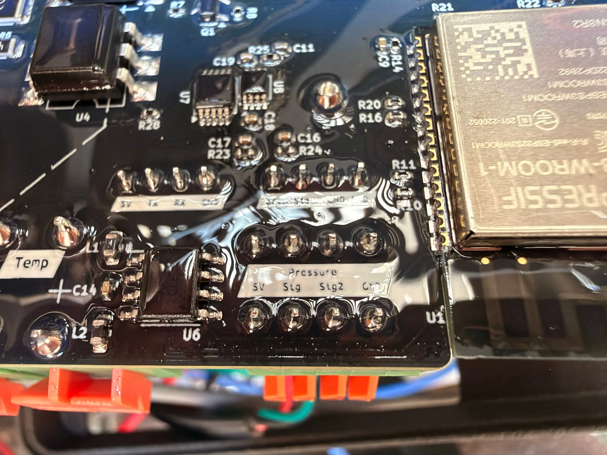
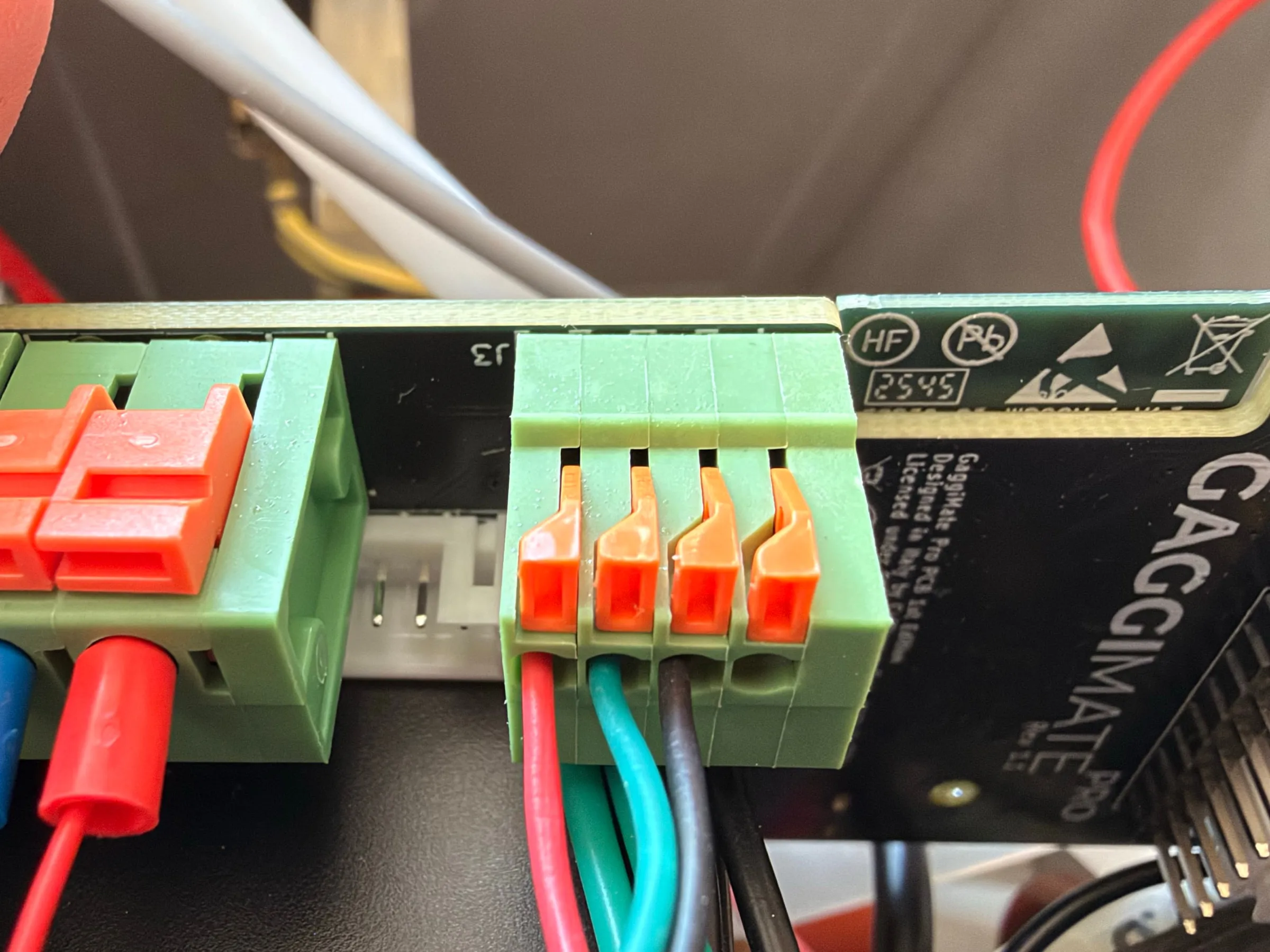 Wrong
WrongAfter the move the brew screen read 27 °C and 0.0 bar, and the 14.1 bar of the evening before was explained: the troubleshooting page's "stuck around 14.5 bars", the black wire without contact.
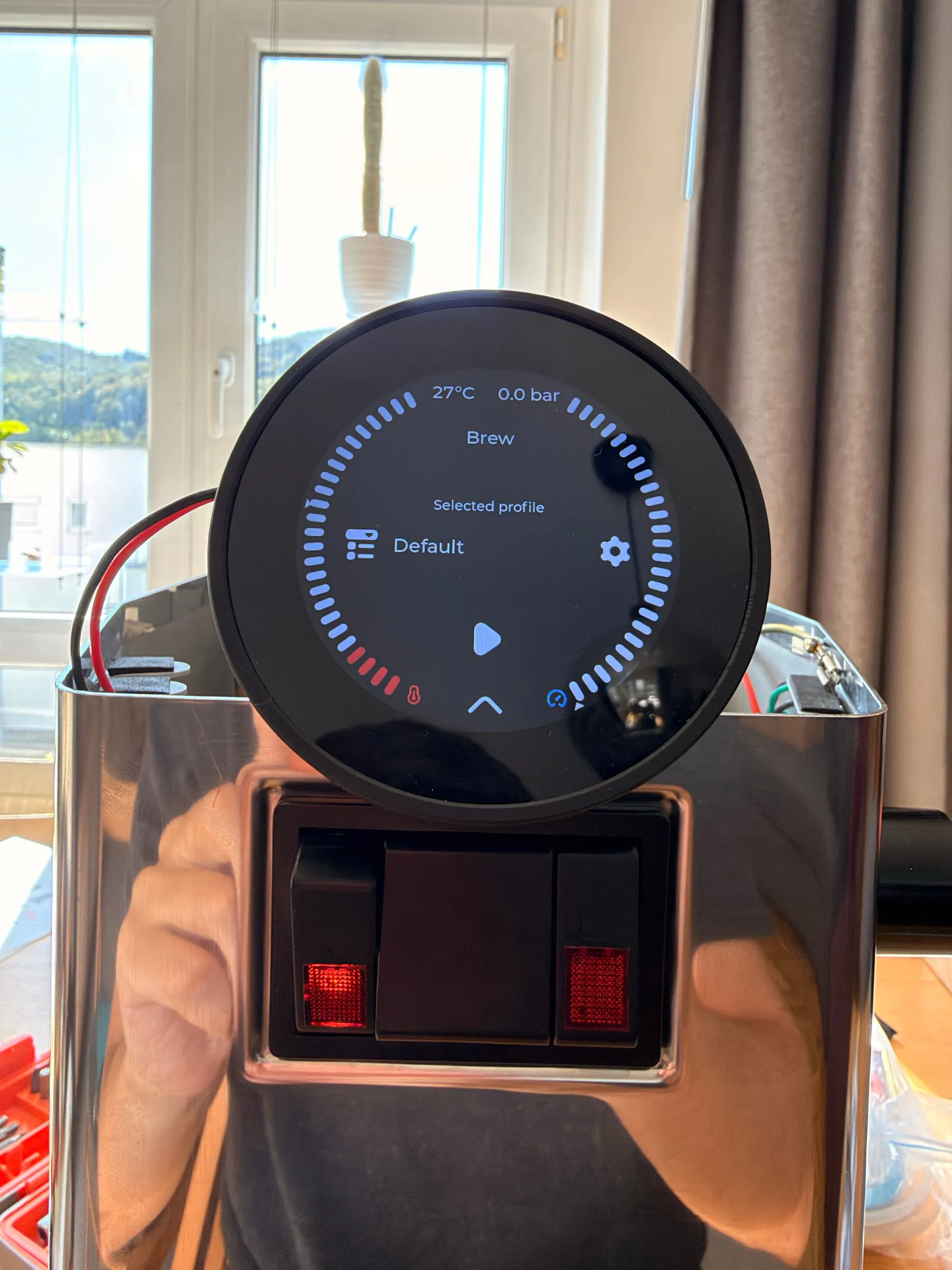
8.Wi-Fi, PID values and the offset
The rest of the setup is the first-start page of the documentation, with two notes from this machine. On first boot GaggiMate opens its own access point named GaggiMate, on v1.8.1 an open network without a password. The same access point comes back whenever the display cannot reach the home Wi-Fi within ten seconds of switching on, and it stays until the next power cycle; the saved Wi-Fi details are kept. The first-start page prints 4.4.4.1 as the address, but the link behind that text points to 192.168.4.1; the firmware and the display both say 4.4.4.1, and that is where it is, so type it rather than clicking. Enter your Wi-Fi there, and after the reboot the machine answers at gaggimate.local.
The temperature control needs two values. The PID values have documented starting points per machine, for the Classic 58.397, 1.027 and 249.055. I ran the autotune from a cold boiler, and it replaced them with 36.526, 0.450 and 389.444, the values the machine brews with as this is written. The offset is the more interesting number. It raises the boiler-wall temperature by that amount over the brew temperature you set, 8 for a Classic, and the firmware applies it in both directions: the boiler is regulated to target plus offset, and the display shows the reading minus the offset. With 93 °C set, the boiler wall runs at 101 °C while the display shows the estimated brew temperature. The offset is a number to touch only once you measure at the puck.
PID autotune, if the starting values do not hold
On v1.8.1 it is its own menu item, PID Autotune. Start it only from a cold boiler, below 50 °C, or it may not finish or may return odd values. The fields are the tuning goal, 0 for conservative to 100 for aggressive with 60 as the default, and the window size, 1 to 10 samples with 4 as the default. The result is saved as soon as the run completes. Newer firmware moves the autotune into the calibration settings with different fields, so check which version you run.
Then the machine heats. The boiler is quick, the brass group head is not: 20 to 30 minutes with the portafilter locked in before the first shot, and the LED on the relay shows the heater pulsing as the PID settles.
First shots and what the firmware does
9.Two shots: 43.3 g and 36.3 g
The stock profile is called "Default" and is as plain as a profile gets: 93 °C, one phase named Brew, valve open, pump at 100 %, 28 seconds, target at least 36 g. The first shot with it, 16 g in the IMS basket, ran for 28 seconds and put 43.3 g in the cup: 1.55 g/s, a ratio of 1 to 2.7. Too much, too fast. What I watched during it was the display: the pressure stood at 8.5 bar from start to finish, exactly the over-pressure valve setting measured with the gauge in Part 1, and the temperature fell from 90 to 88 °C against the 93 °C target, which is the reading minus the offset while fresh tank water runs into the boiler. At 0:28 the display said Finished, the light ring turned green, and the residual pressure read 3.2 bar.
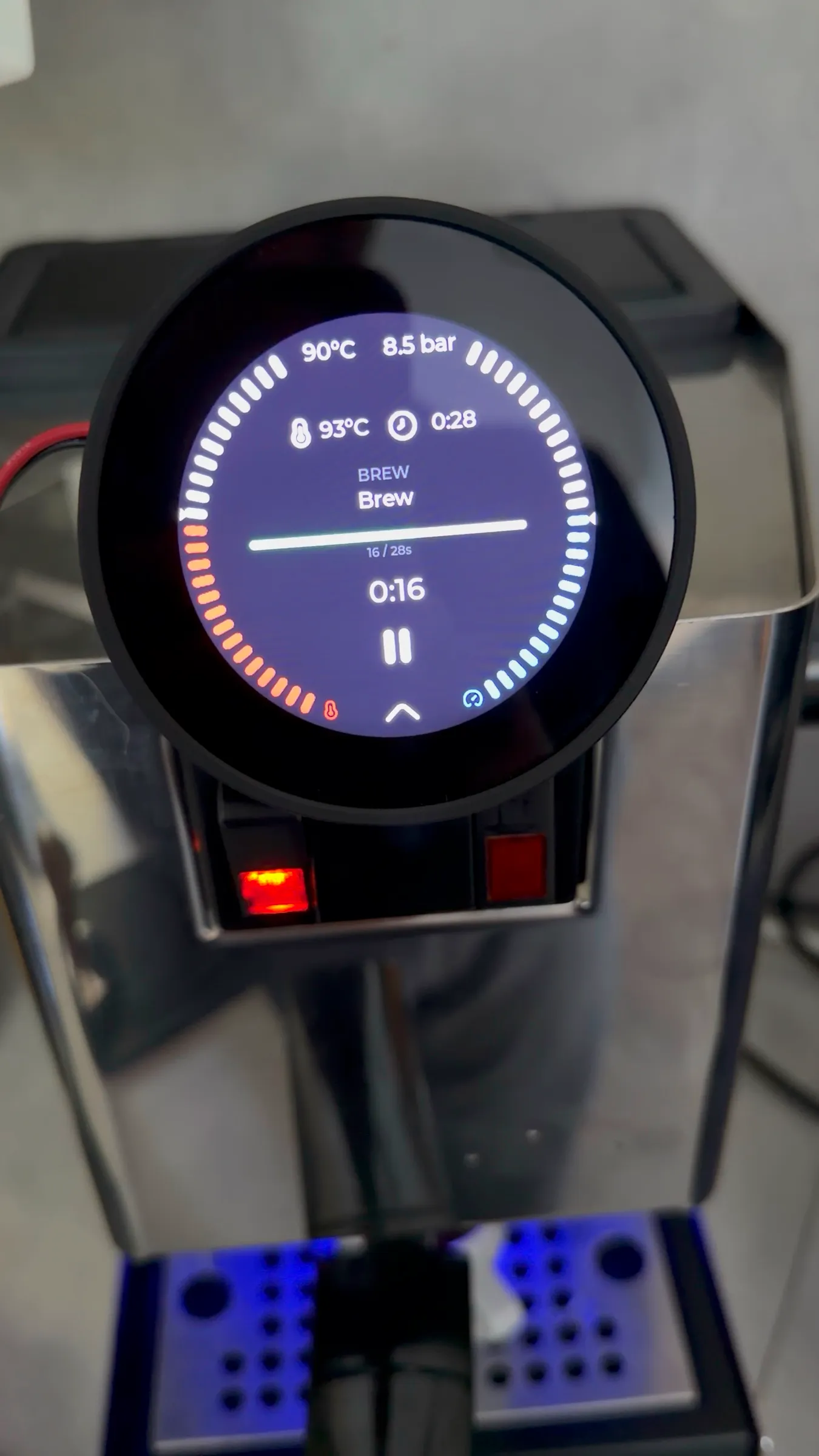
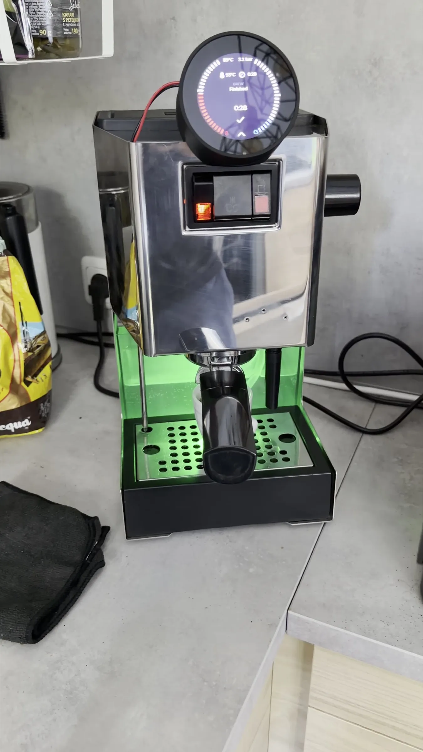
For the second shot I left the grinder alone and pressed the minus button on the brew screen twice, which took the duration from 28 to 26 seconds. Same dose, same grind, two seconds less: 36.3 g, 1.40 g/s, a ratio of 1 to 2.27. The lower yield came from the shorter time, not from finer coffee; the flow rate barely moved. The corridor I want for a starting recipe is 30 to 32 g in about 28 seconds, roughly 1.1 g/s, and the way there is a finer grind, not a shorter timer. One side note from that session: afterwards the web interface listed two profiles named Default. I assume I touched a save-as-copy control on the display while changing the time, but I could not reconstruct it.
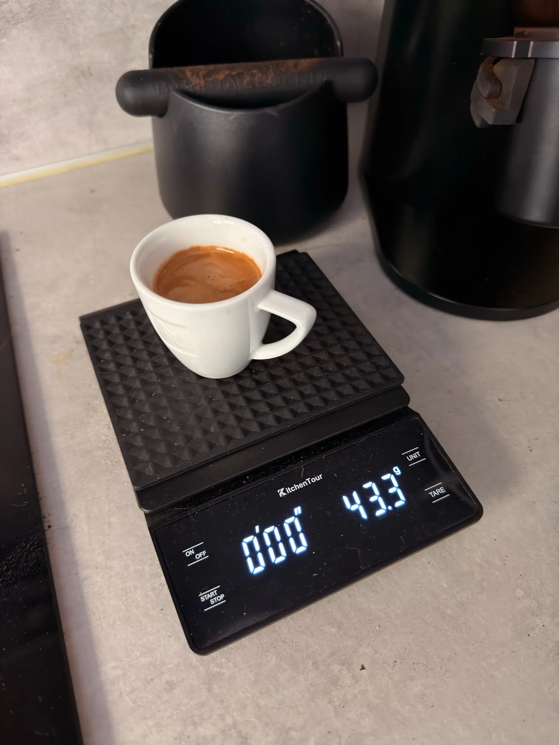
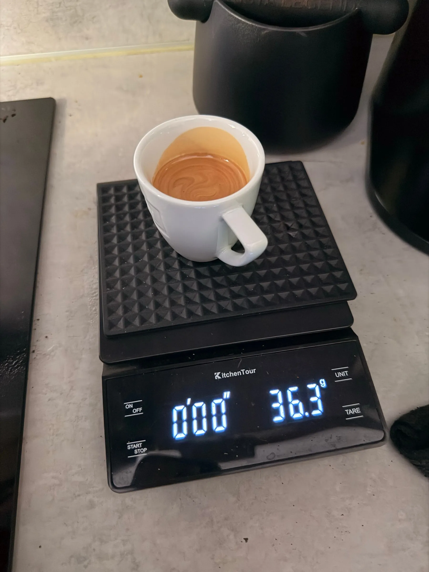
10.What "stop at 36 g" means without a scale
The profile promised a stop at 36 g and delivered 43.3 g, and the reason is simple: in the release firmware a shot can only be ended by weight when a Bluetooth scale is paired and healthy. Without one, the shot starts as a time target: the phase duration counts, and the weight target is never looked at. With a scale it is the other way round for a standard profile: the weight ends the shot, the duration is not checked, and only the safety cut-off after five minutes remains. So a profile that reads like a recipe is, without a scale, a stopwatch, and the yield on my worktop is set by the grind alone.
Where this is in the source
In the firmware repository, read on the master branch in September 2026 while the machine runs the v1.8.1 release, the check that decides whether a volumetric stop is available returns nothing but the health of the Bluetooth scale. Nightly and release builds are the same source; a compile flag makes the difference, and only with it is the flow estimate allowed as a stop source, and then only while no healthy scale is connected. Without the flag the estimate is display only. The stock profile "Default" is defined in the same repository: 93 °C, one brew phase, valve open, pump 100 %, 28 s, target at least 36 g. The five-minute cap is a constant, and the plus and minus buttons call a function that adjusts the profile's duration by one second when there is no weight target to move.
The Pro does something the Standard cannot: it estimates the yield while the shot runs, and it does that from the pressure curve, not from a flow meter. The pressure controller models the group as a small reservoir: what the pump delivers and does not go into building pressure must be flowing through the puck. The puck's resistance is estimated continuously, and once it settles after the first drops the flow through it is summed up. For that it needs to know what the pump delivers at a given pressure, which is what the two pump flow coefficients in the settings are: 10.205 and 5.521 ml/s at 1 and 9 bar, the firmware's defaults, which this machine still runs on. Nothing adjusts them by itself: without a scale the estimate never sees a real yield, so it does not get more accurate with use. Calibrating it means comparing the estimate in the shot history with the weighed cup over a few shots and scaling both coefficients by the ratio; a calibration assistant on the master branch does this with a Bluetooth scale. The model also has no term for the over-pressure valve: when the pressure sits at the valve's setting, as in the stock profile, part of the flow goes back to the tank and the estimate reads high, so the comparison belongs to profiles below the valve. The result is a volume in millilitres, not a weight in the cup, and it starts counting at the first drop, not at the pump. GaggiMate records it with every shot as its own curve in the shot history, next to the scale's value if there is one, so even on the release build you can see how close the model gets to what you weighed.
How a volumetric stop lands on target
Because liquid is still on its way to the cup when the target is reached, the firmware stops early: it fits the flow rate over a four-second window and ends the shot about 0.8 s before the target, a value called brew delay, capped at a predicted overrun of 8 ml. After every volumetric shot it rewrites that delay from the overrun, within 0 to 4 s, measured by whatever stopped the shot: with a scale that is the cup, with the estimate it is the estimate itself. The stop gets more punctual over time; the estimate does not get more accurate. The same mechanism exists for grinding. On the release build this lead applies to the stop by scale; the estimate may end a shot only on nightly builds and only without a scale, so without a scale the numbers above stand, and the estimate is a second opinion that is written down every time.
The self-test
11.A self-test profile for the machine
The idea came from the readings of the day before. The Pro knows the pressure between pump and boiler at all times, and a profile can open the valve, run the pump and stop it in any order I like. So a profile can be a function test: lock in the blind filter, start it, and watch what the display does in each phase. Claude wrote the profile to that idea, checked against the firmware's profile schema; I ran it and read the display. The profile is in the download box in the last step, in English and in German, and imports under Profiles with "Import profiles"; favourite it so that it shows on the display. Case still open for the first run, tank full, no coffee.
| Phase | Duration | Valve, pump | What to expect |
|---|---|---|---|
| 1.Idle | 5 s | closed, off | Everything quiet. The reading is boiler pressure: about 0 bar cold, a few bar warm |
| 2.Valve opens | 4 s | open, off | An audible click; warm, the pressure drops to 1 to 2 bar as it spreads into the group |
| 3.Pump to group | 12 s | open, 100 % | The pressure rises within a few seconds to the over-pressure valve's setting and holds |
| 4.Hold pressure | 6 s | open, 100 % | The pressure sits still, every fitting dry |
| 5.Hold, pump off | 8 s | open, off | The pressure gives about 1.5 bar in the first few seconds, then holds. If it keeps falling, something leaks |
| 6.Valve closes | 4 s | closed, off | A second click, the group is relieved into the drip tray; the reading stays put. If it drops by several bar, the boiler-side seat of the solenoid valve is not sealing |
Phase 3 has a target of 11 bar that this machine can never reach, so the phase always runs its full 12 seconds; the target is a safety limit: should the pressure ever get there, the phase ends at once. The profile is of type standard and carries the utility flag, like the "[Utility] Backflush" profile that ships with the firmware, so it sorts with it.
The first run, on the morning of the 24th, read like this. The numbers are Claude's: I filmed the display, and it went through the video second by second and wrote the readings down, which I then checked against the frames. 3.7 bar in the idle phase at 96 °C; down to 1.2 bar when the valve opened; up from 1.1 to 8.6 bar in about four seconds when the pump started, then 8.6 to 8.8 bar flat, which is the 8.5 bar of the gauge from Part 1 with the sensor's own opinion; Finished after 35 seconds with 1.6 bar standing and the housing dry.
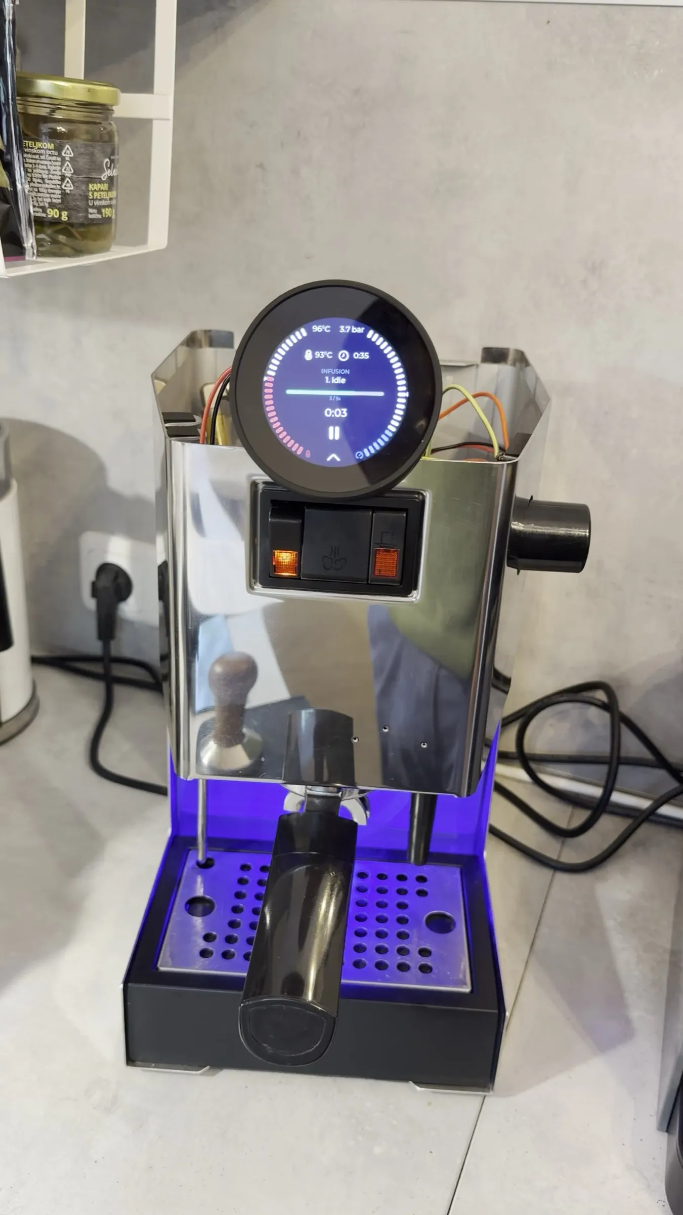
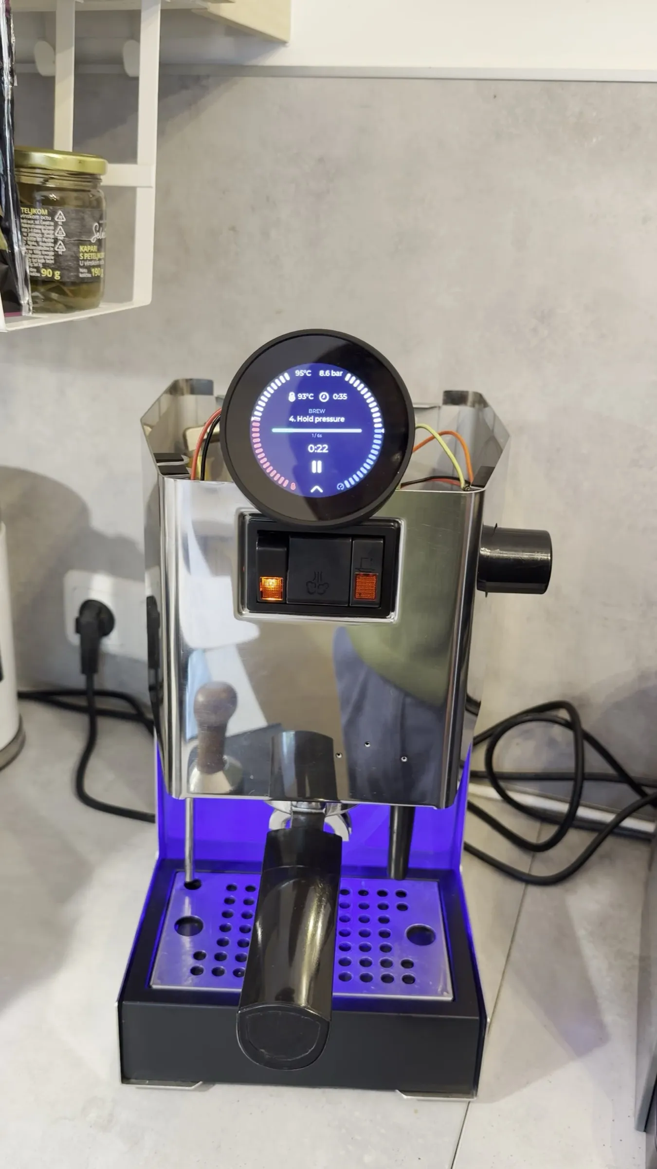
The first run also changed the profile. Its first version had a fifth phase that ran the pump at 60 % against the closed valve, which tests nothing that the other phases do not, and it had no phase in which anything had to hold pressure without the pump. So phase 5 became "Hold, pump off": eight seconds, valve open, pump off, the actual leak test at full pressure, and only then does the valve close. The second run with that profile is the clip above and the result that matters: when the pump stops, the pressure gives once, from 8.6 to 7.2 bar, and then stands for five seconds without moving. The circuit is tight.
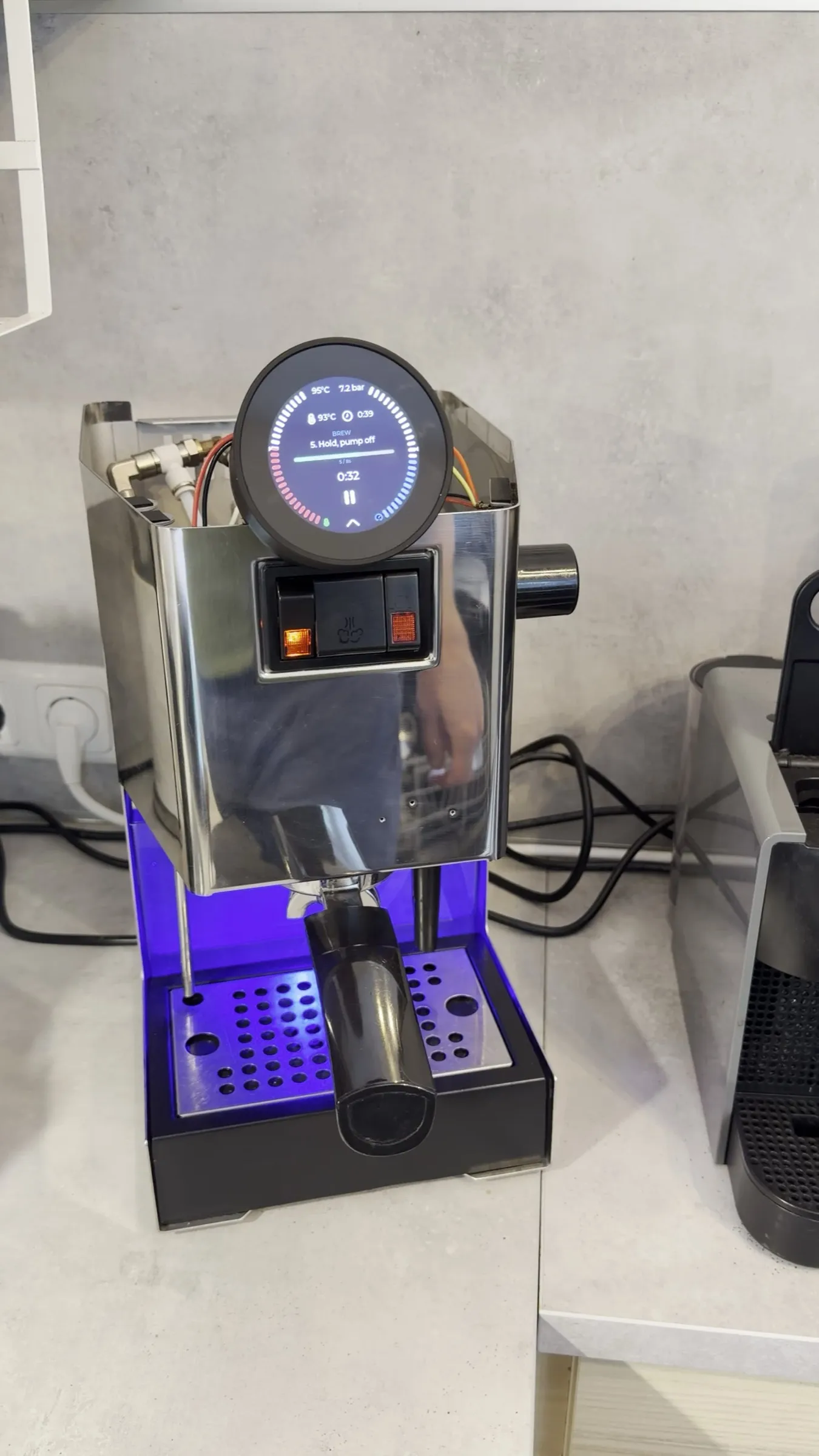
Rectangles on the display, and a crash in the core dump
Two things went wrong before the profile ran. The first version's name contained a middle dot, and the display drew empty rectangles for it. The firmware draws with the built-in Montserrat fonts of its graphics library, and those contain ASCII, the degree sign and the bullet, nothing else: no middle dot, and no umlauts either, so the German profile is called "Selbsttest" and describes itself without ä, ö and ü. Profile names for the display are ASCII names.
The second was a crash on the display before any test had run. The support file from the web interface contains the ESP's core dump, and a small script Claude wrote read it without the toolchain: the UI task had aborted with a range-check message from the C++ runtime, an access to element zero of an empty list. As far as Claude could read the source, the only place that reads element zero of a phase list is the constructor of the brew process, so the selected profile had no phases at that moment; the profile manager does not check whether loading the selected profile succeeded, and a failed load leaves an empty profile behind. With the profile imported again the test ran without a crash, and the two support files stay in the project folder in case the developers want them.
12.The pressure sensor as a leak detector
Phase 6 of the second run raised the question that phase 5 had answered for everything else. When the valve closed, the display fell from 7.2 to 3.2 bar in about three seconds and then stood at just under 3 bar. Why should the boiler pressure fall when the valve between boiler and group closes? So a third run, with the grid off the drip tray and the phone on the solenoid valve's drain pipe.
Phase 5 held again: 8.6, 7.9, 7.4, 7.1, 6.9 bar over about three seconds, then four seconds at 6.9 to 6.8 bar. Then the click, and the display fell 6.8, 5.0, 3.1, 2.5, 2.3 bar, and in exactly those three seconds a jet of water ran from the drain pipe into the tray, followed by single drops. The sound track, which Claude also went through, says the same: the click, a second of hiss, a second of splashing. And in the idle state afterwards the reading kept sinking, 2.2 to 1.8 bar over nine seconds, although the heater was on and the water expanding.
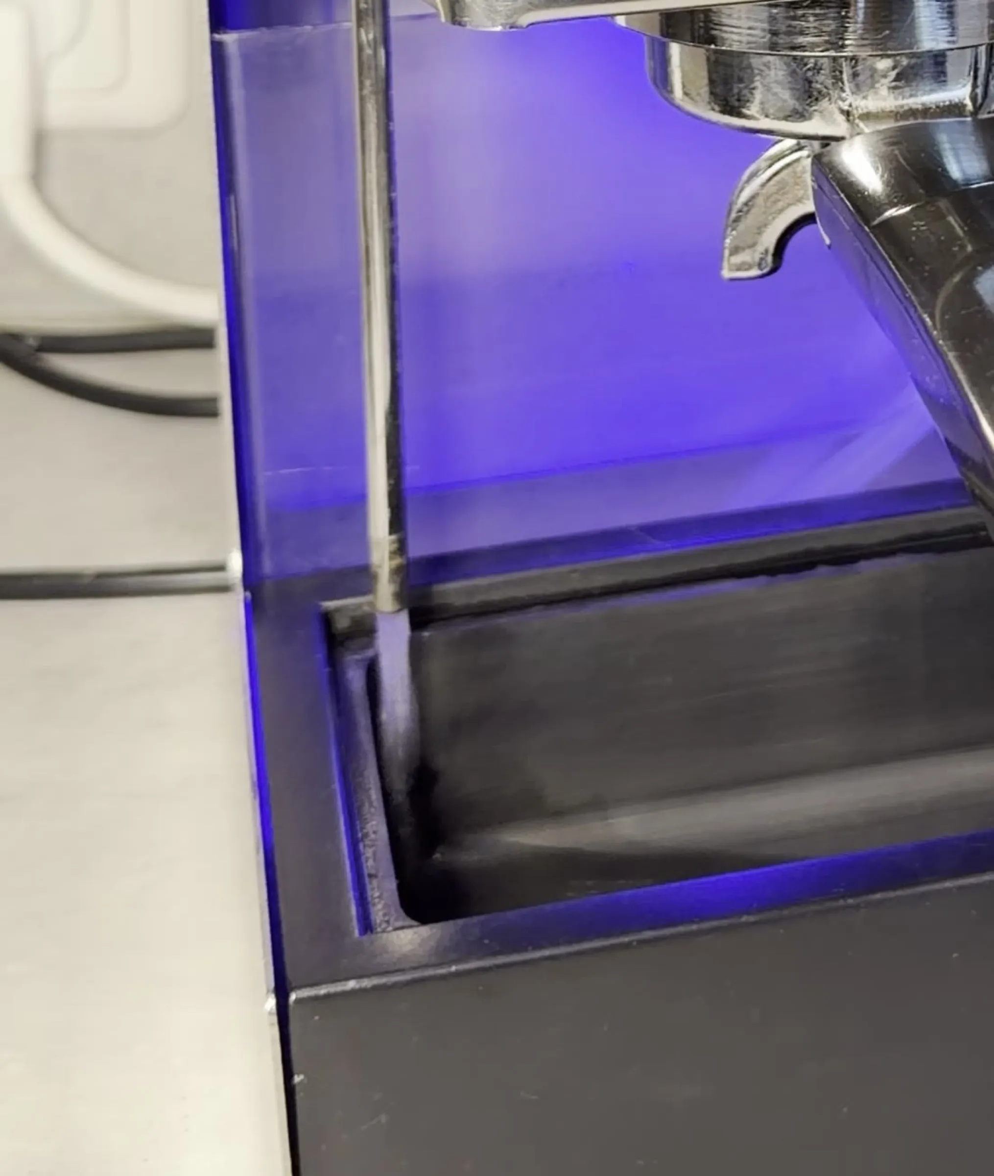
The conclusion that follows is Claude's, built by exclusion from the three videos: it read the display second by second, listened to the sound track for the clicks and the hiss, and put the phases side by side. I filmed and I am not sure the conclusion is right. Phase 5 shows that pump, over-pressure valve and every fitting hold pressure without the pump. In phase 6 nothing changes but the position of the three-way valve. So the boiler water can only reach the drain through the valve's boiler-side seat, which then does not close fully: fast at high pressure, slow at 2 bar. Whether that is a fault of this valve or simply how a valve of this kind behaves, neither of us can say yet. For the shot itself it does not matter, the valve is open then. The next time the valve is apart, the seat and the plunger seal get a close look, and the self-test runs again. If phase 6 then holds, it was dirt on the seat. If the reading falls by several bar again, either the seat is worn, or my assumption is wrong and this is normal for the valve.
The caveats, spelled out
These are Claude's own reservations about its conclusion. The water from the drain pipe is mostly normal: after the "pfft" the group drains, and that takes a second or two. To lower the boiler pressure by 4 bar takes very little water, an estimated fraction of a millilitre, which no camera would separate from the group draining. The hint comes from the pressure, not from the jet: a fall of 4 bar in three seconds at the moment the valve closes, and a slow decline afterwards against a heating boiler. A mere switching loss would be over in milliseconds, and the display filter of the firmware follows a step within about half a second, so the fall is real. A matching three-way valve from OLAB is rated to 15 bar, so a closed one should hold 7. What is open: I have no comparison run on a Classic with a valve known to be tight, and the assumption that nothing shuts off between the sensor's tap and the boiler comes from the installation guide, not from my own check. If either does not hold, the conclusion does not either, and the behaviour may be normal for this valve. The next step is the same in every case: clean the valve and run the test again.
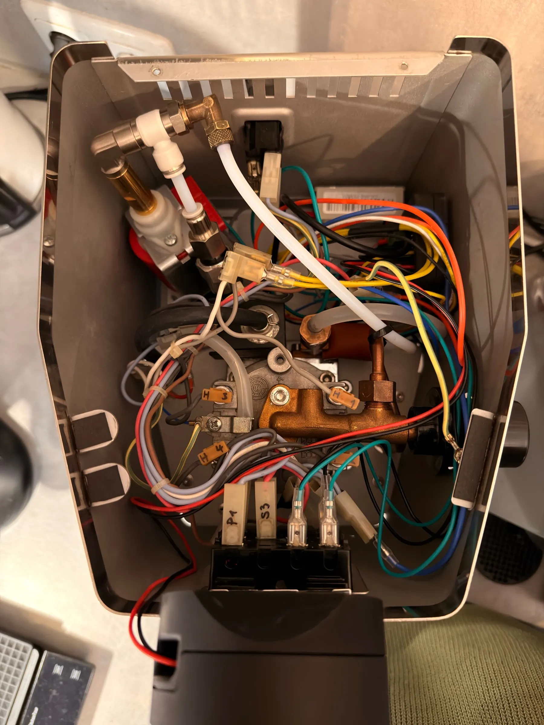
The quick-start guide
13.Two pages for the kitchen drawer
The documentation is good, and it is a website. What I wanted next to the machine is two pages that hold everything a person has to know to run this particular machine, including the three things the documentation does not know: that the pressure sensor is wired, that the over-pressure valve sits at 8.5 bar, and that the ready lamp means nothing any more. So there is now a quick-start guide, in German for the kitchen and in English for this article, two A4 pages each. Claude wrote it, from the documentation, the firmware source and my notes, and built the script that generates the PDF from a text file, so that a change is a line in a file and a rebuild, not an afternoon in a layout program. I reviewed every line against the machine.
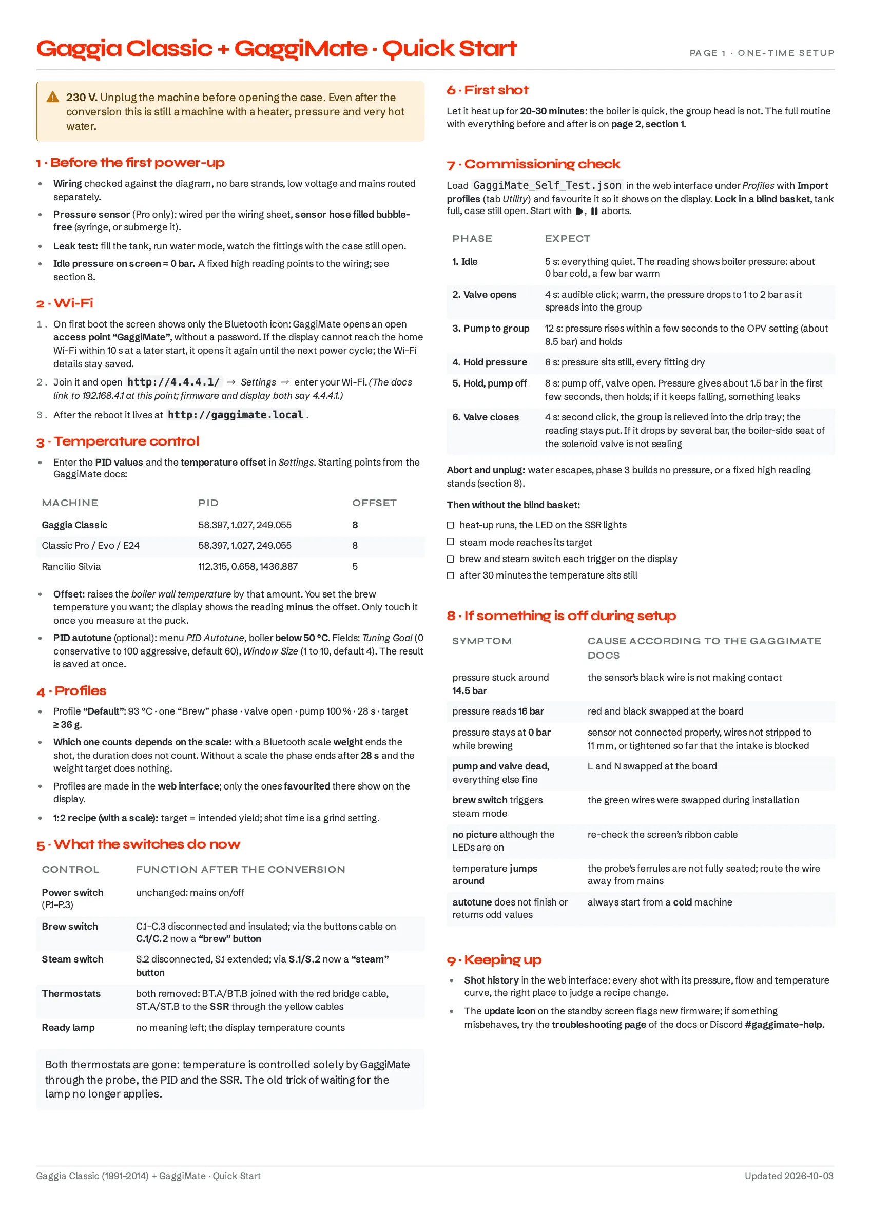
Page 1 is the setup: the checks before the first power-up, Wi-Fi with the 4.4.4.1 note, the PID starting values and what the offset does, the stock profile and why weight only counts with a scale, a table of what each switch now does, the first shot, the self-test table from step 11 as a checklist, the setup faults from the troubleshooting page, and where to look for updates and help.
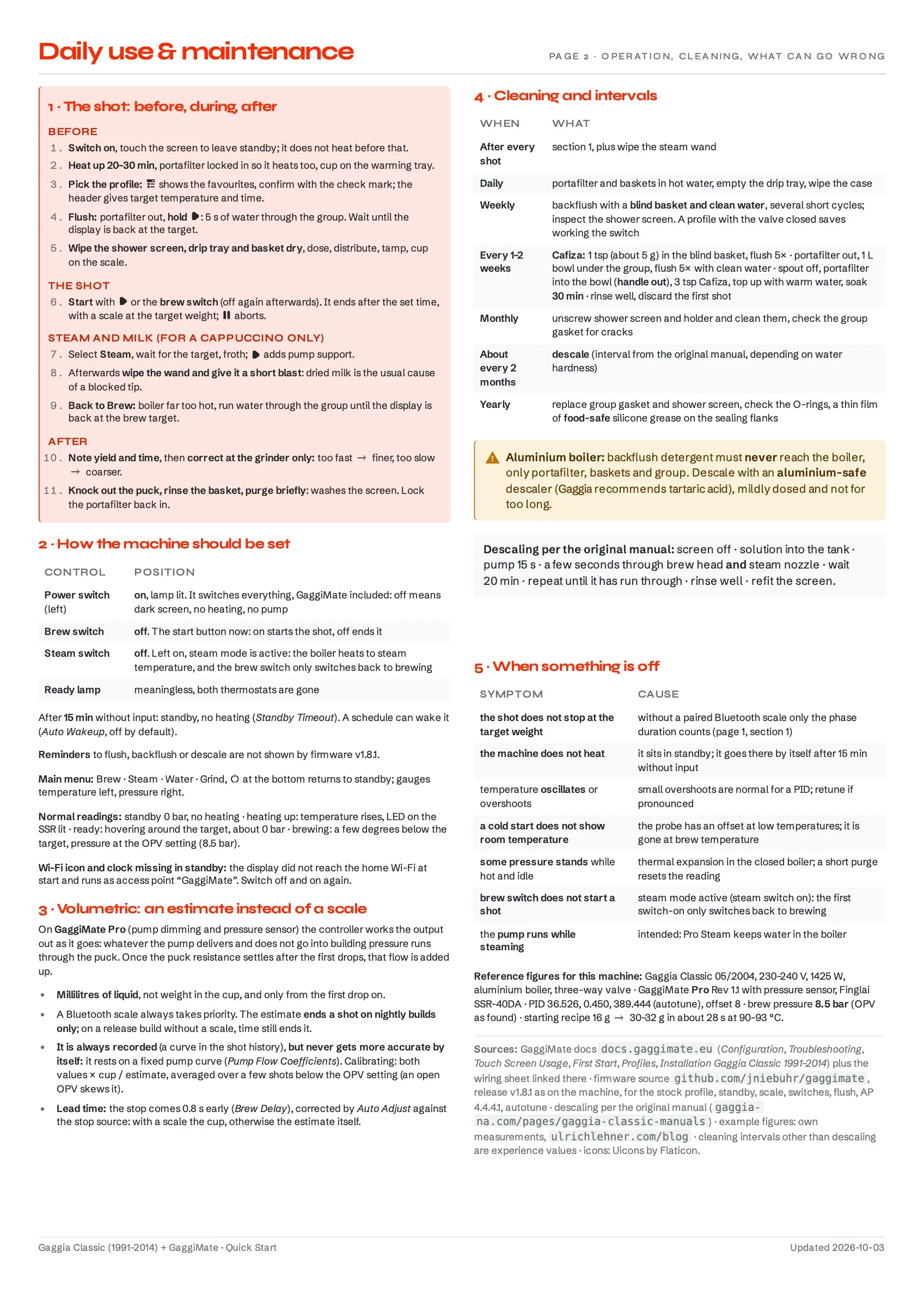
Page 2 is the daily use: the shot routine before, during and after, in eleven numbered lines; how the machine should be set, which is the power switch on and both other switches off; the volumetric estimate and how to calibrate it by hand; cleaning and intervals from after every shot to yearly, with the warning that backflush detergent must never reach the aluminium boiler and that the descaler has to be aluminium-safe; the faults of daily life; and one line of reference figures for this machine, so that a second copy for a different Classic only needs that line changed.
What the guide is built from
The contents come from the GaggiMate documentation, its configuration, troubleshooting, touch-screen, first-start, profiles and installation pages plus the wiring sheet linked there; from the source of the v1.8.1 release that runs on the machine for the stock profile, standby, the scale logic, the switches, the flush and the access point address; and from the original Gaggia manual for descaling. The example figures are my own measurements. The cleaning intervals other than descaling are experience values, not manufacturer numbers. The display icons on the pages are the ones the firmware shows, Uicons by Flaticon, used with attribution; the arrow, warning and checkbox symbols are drawn for the guide, and the fonts and colours are this website's.
What comes next
The machine now holds its temperature, shows its pressure, and tells me when it has finished. What it does not do yet is look tidy inside or brew from a profile that was designed rather than inherited. The first own profile exists, for a dark Neapolitan blend: a fast fill and five seconds at 3 bar, a peak at 7.5 bar, deliberately under the over-pressure valve, and a linear decline to 5.5 bar. It started at 90 °C on the assumption that a dark roast wants cooler water, and its first shot, 33.4 g from 16 g, was slightly bitter. A temperature series with the stock profile then pointed the other way: with the same beans, dose and grind, 96 °C tasted much better than 93 °C, which fits a stock thermostat that ran the boiler hotter than the PID does now. The profile runs at 96 °C since. That is the material for Part 3: profiles that earn their phases, and with them the question whether the over-pressure valve goes up to make room for 9 bar, cable management, a better place for the board and the display inside the housing, the badge on a mount that does not bend its tabs, magnets if I find a way, the solenoid valve's seat cleaned and the self-test run again, calibrating the pump flow coefficients against the cup, a replacement steam thermostat for the drawer (under ten euros, so that the machine can go back to stock one day), and the question whether a Bluetooth scale earns its place next to a machine that can count seconds.
Sources and further reading
None of this is original knowledge. These are the pages, repositories and documents this part leaned on, roughly in the order they were needed.
GaggiMate documentation (7)
- Installation: Gaggia Classic (1991 to 2014), the guide for this machine, with the wiring sheet whose connector names the labels above use.
- Wiring, the board's connections, including the pressure sensor's terminal row.
- First Start, the access point, the Wi-Fi setup and the first heat-up.
- Configuration, the PID starting values per machine, the offset and the autotune fields.
- Touch Screen Usage, the brew screen and the buttons.
- Profiles, phases, targets and the import in the web interface.
- Troubleshooting, the source of the 14.5 bar, 16 bar and 0 bar diagnoses and of the faults table on page 1 of the guide.
Firmware, shop and display (5)
- jniebuhr/gaggimate, the firmware source, read on the master branch as of 22 September 2026 while the machine runs the v1.8.1 release: the stock profile, the scale logic behind the 36 g, the flow estimate, the access point address, the crash, and the v1.8.1 tag for the flow estimate, the pump coefficients and the delay adjustment.
- jniebuhr/gaggimate-docs, the documentation source, from which the print PDF of the installation guide was built.
- GaggiMate shop, Pro kit, where the kit came from and where the list price above is from.
- LVGL: Fonts, the graphics library's documentation, which explains the rectangles: the built-in Montserrat fonts hold ASCII, the degree sign and the bullet.
- Uicons by Flaticon, the display icons the firmware uses and the quick-start guide reuses; the licence asks for this credit.
Gaggia documents and parts (3)
- Gaggia North America: Gaggia Classic manuals, the original manual, the source of the descaling procedure on page 2 of the guide.
- The official parts diagram ER0182, for the thermostat positions.
- Avola Coffeesystems, the component list for the Classic with part numbers, where the thermostats are listed.
Working with Claude
As in Part 1, I did not do this alone, and this part leaned on Claude, Anthropic's AI assistant, more than the restoration did, because the questions moved from parts on a table to code in a repository.
Concretely, it built the print PDF of the installation guide from the documentation's source files, with a script that reproduces it from any revision. It kept the project notes after every session; this article is written from them. When the stock profile did not stop at 36 g, it read the firmware source and found the condition that makes weight count only with a scale, and later the model behind the Pro's yield estimate. It read the three self-test videos frame by frame, wrote down the display readings second by second and followed the sound track for the valve clicks, which is what the leak argument in step 12 is built on. It read the support file with the core dump without a toolchain and traced the crash to a profile without phases. It checked the self-test profile against the firmware's schema and against the display font's character set, which is how the middle dot was found, and it wrote the first drafts of the quick-start guide and of the profiles, including the phase that turned the self-test into a leak test.
Two limits are worth stating. Reading source code is not the same as measuring: the numbers in this article are from my display, my scale and my videos, and the source only explained them. And the leak conclusion in step 12 is Claude's argument by exclusion; it is provisional, and it will be confirmed or corrected by a cleaned valve, not by another paragraph.