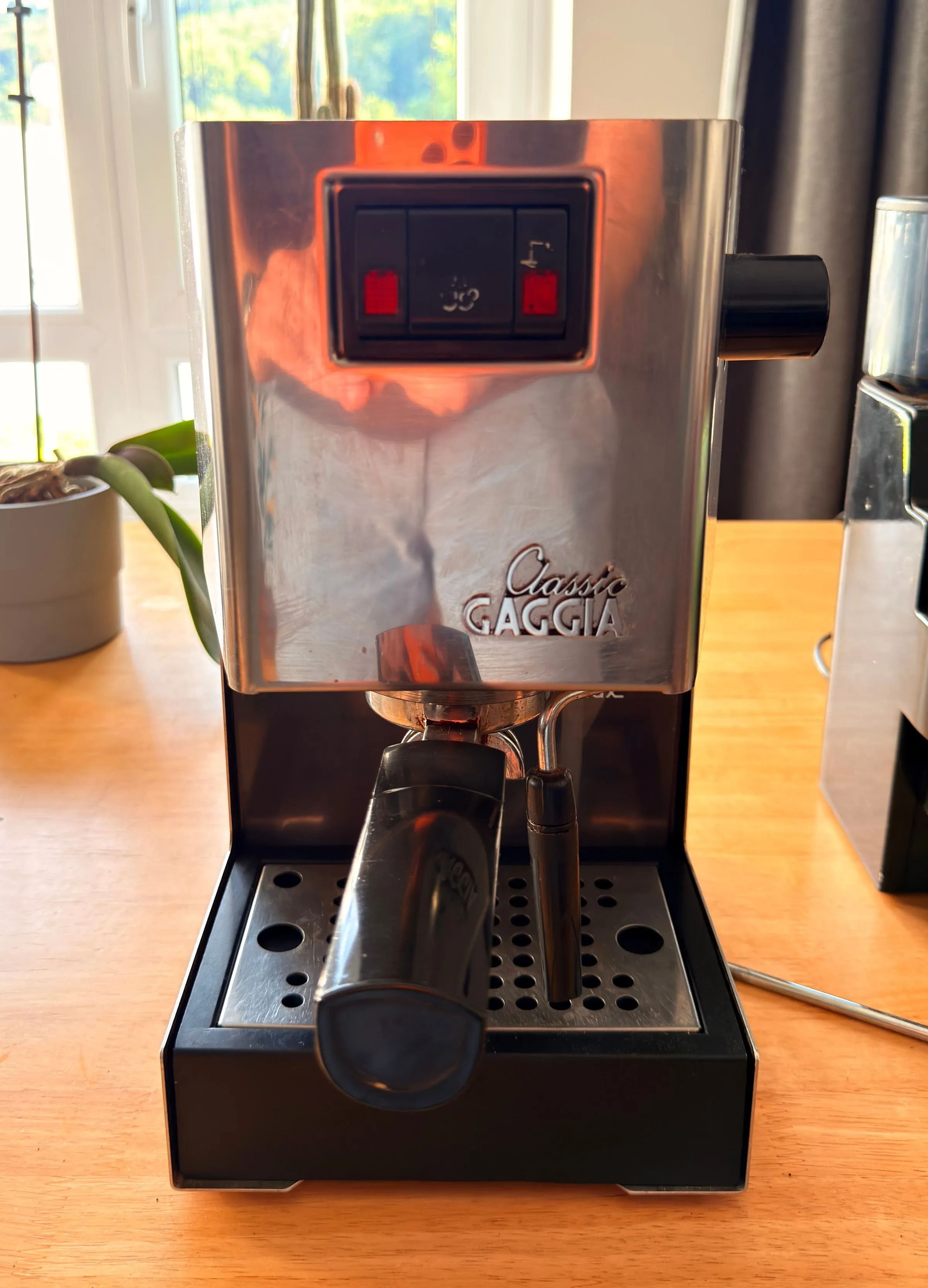
In July I drove out to the Innviertel with EUR 200 in my pocket and came back with a Gaggia Classic and its matching grinder: a working machine, about twenty years old and due for a full service. Around 50 hours of work later, most of them in one week in July, it made its first espresso again.
This is Part 1 of two: the mechanical restoration, from the find to the first shot. Part 2 will be about the GaggiMate, the PID controller that replaces the 2004 thermostats.
| Item | Detail |
|---|---|
| Machine | Gaggia Classic |
| Built | 05/2004, Made in Italy (Robecco sul Naviglio, Milan) |
| Inside | Aluminium boiler, 230 to 240 V, 1425 W, 3-way solenoid valve, Ulka vibration pump |
| Bought | 12 July 2026 on willhaben, EUR 200 including a Gaggia grinder |
| Plan | Reseal, descale, treat the rust, polish. Then the PID conversion (Part 2). |
The project at a glance
A machine of this age rarely needs new parts. It needs a full service: everything that carries water descaled, every seal renewed, every screw replaced, the rust on the steel base converted and sealed, the housing polished. These are the steps in the order I would do them again; each row links to its section.
| Step | What it involved | Rough effort |
|---|---|---|
| Before the teardown | ||
| 1.Check and measure | Type plate, a look inside, four multimeter readings, the solenoid test · 5 images, 1 clip | One evening |
| 2.Research and the shopping list | Three restoration videos, the parts diagram, one order per shop · 1 image | Two or three evenings |
| Taking it apart | ||
| 3.Teardown: label everything | Label every cable, photograph every step, boiler and group out · 9 images | About 3 hours |
| 4.The boiler that would not open | Penetrating oil, heat and a manual impact driver · 5 images | About 4 hours over two days |
| Cleaning, rust and paint | ||
| 5.Rust, descaling and polishing | Rust converter on the base, Cafiza baths, descaler, mirror polish · 6 images | About 6 hours |
| 6.Fine cleaning: citric acid and verdigris | Several short rounds of descaler, citric acid, both valves apart · 4 images | About 4 hours |
| 7.Paint and the oven | Masking, thin coats of heat paint, 220 °C in the kitchen oven · 4 images | About 4 hours |
| Fine work: the sealing face and the valve | ||
| 8.Lapping and the over-pressure valve | Sealing face lapped on taped-down paper, OPV apart, turns counted · 7 images | About 3 hours |
| Putting it back together | ||
| 9.Reassembling the boiler | New seals by the lubrication plan, stainless screws with copper paste · 6 images | About 4 hours |
| 10.Wiring and commissioning | Contact spray, wiring by label, water first, leak checks, pressure test · 3 images, 1 clip | About 5 hours |
| Epilogue, two weeks later | ||
| 11.A new pump and 8.5 bar | An Ulka EX5 with a brass outlet, PTFE tape on the elbow, 8.5 bar · 6 images | About 4 hours |
The hours are estimates from the timestamps of my photos: about 50 in total, more than half in one week in July. The calendar says 52 days from purchase to first shot, but on most of them the machine only waited: for parts, for a free evening, for the paint to cure.
It cost EUR 200 for the machine and the grinder, plus EUR 162 for the espresso-specific parts in two orders: EUR 75 to espressoXXL in July for the maintenance set, two precision baskets and a blind filter, EUR 87 to Avola in September for the new pump, the brass shower holder, a pump mount, a portafilter pressure gauge and two spare gaskets. Chemistry, paint, screws and the two tools for the boiler screws came from Amazon and the hardware store, not added up.
Before the teardown
1.Check and measure
The find
The willhaben listing offered a Gaggia Classic with the matching Gaggia grinder: a private sale, both well kept, regularly descaled and working, collection only, the previous owner moving on to a bean-to-cup machine. We agreed on EUR 200 for the pair. However well a machine of that age has been looked after, it is due for a full service, so the plan was set before I got home: look inside first, measure second, order parts third.
A look inside
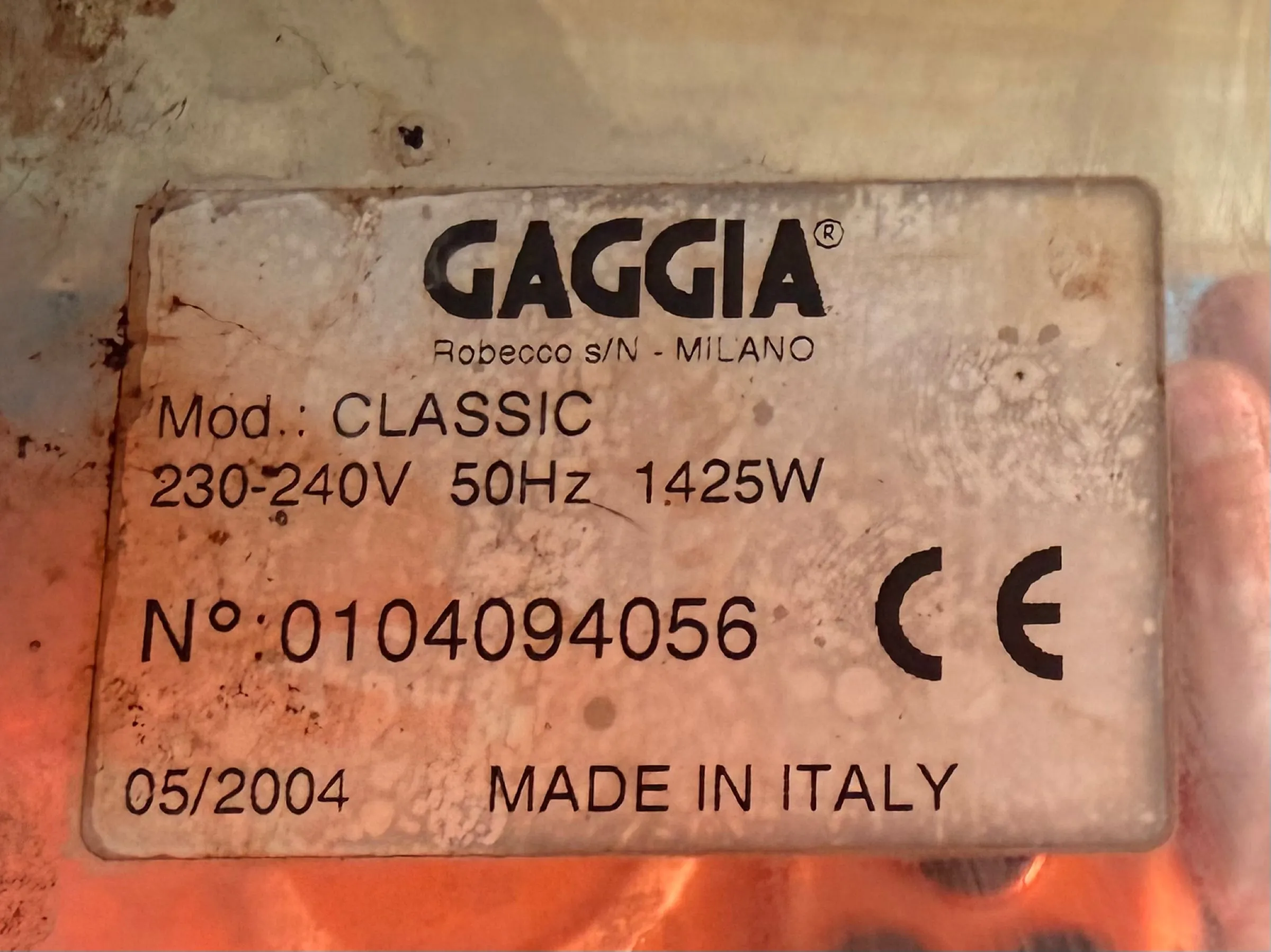
The next morning I turned it over. The type plate is the birth certificate: model CLASSIC, 230 to 240 V, 50 Hz, 1425 W, built 05/2004, Made in Italy. The listing had guessed 2002, easy to get wrong after two decades; both years belong to the sought-after Italian series from before the Philips era.
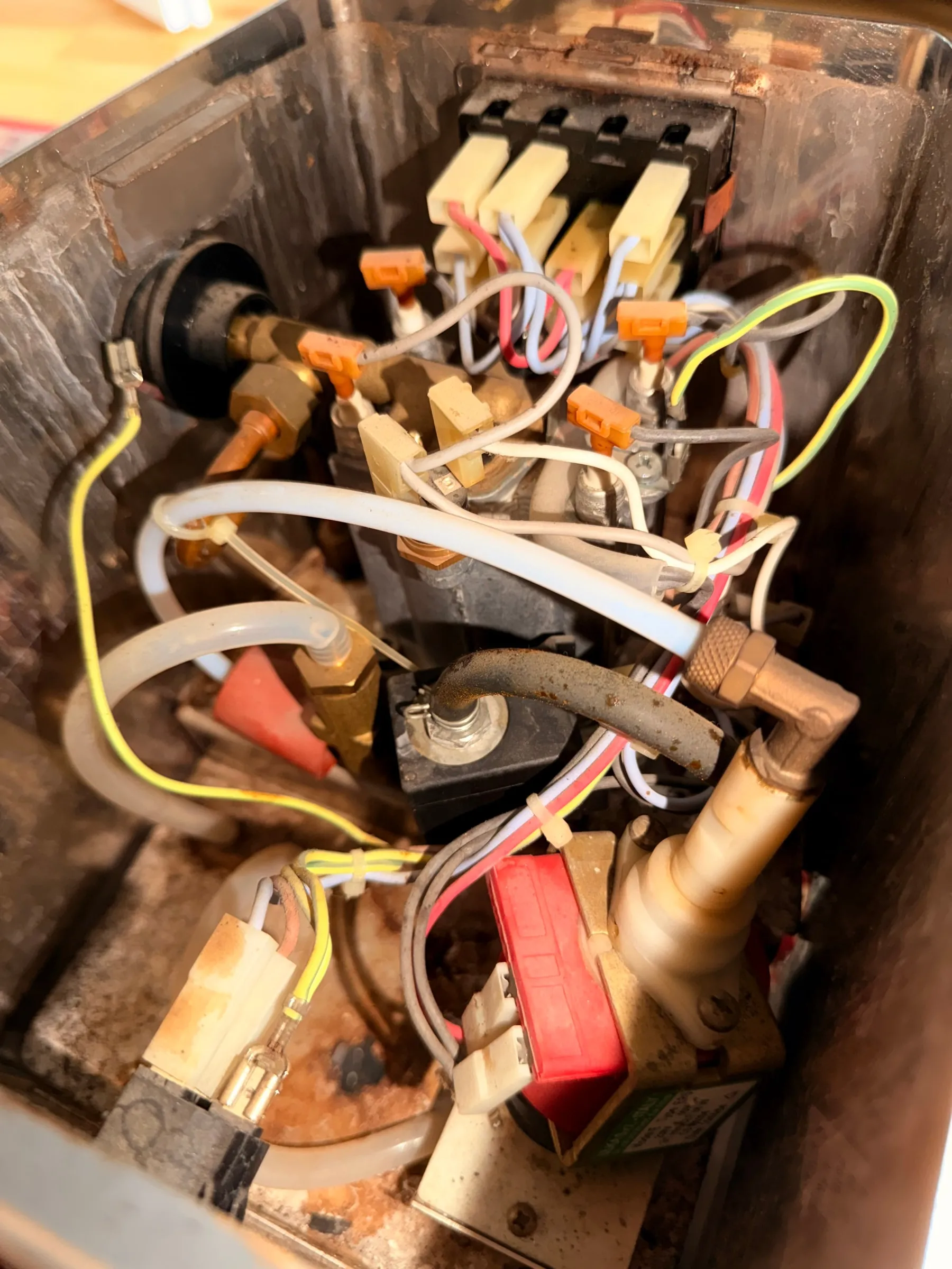
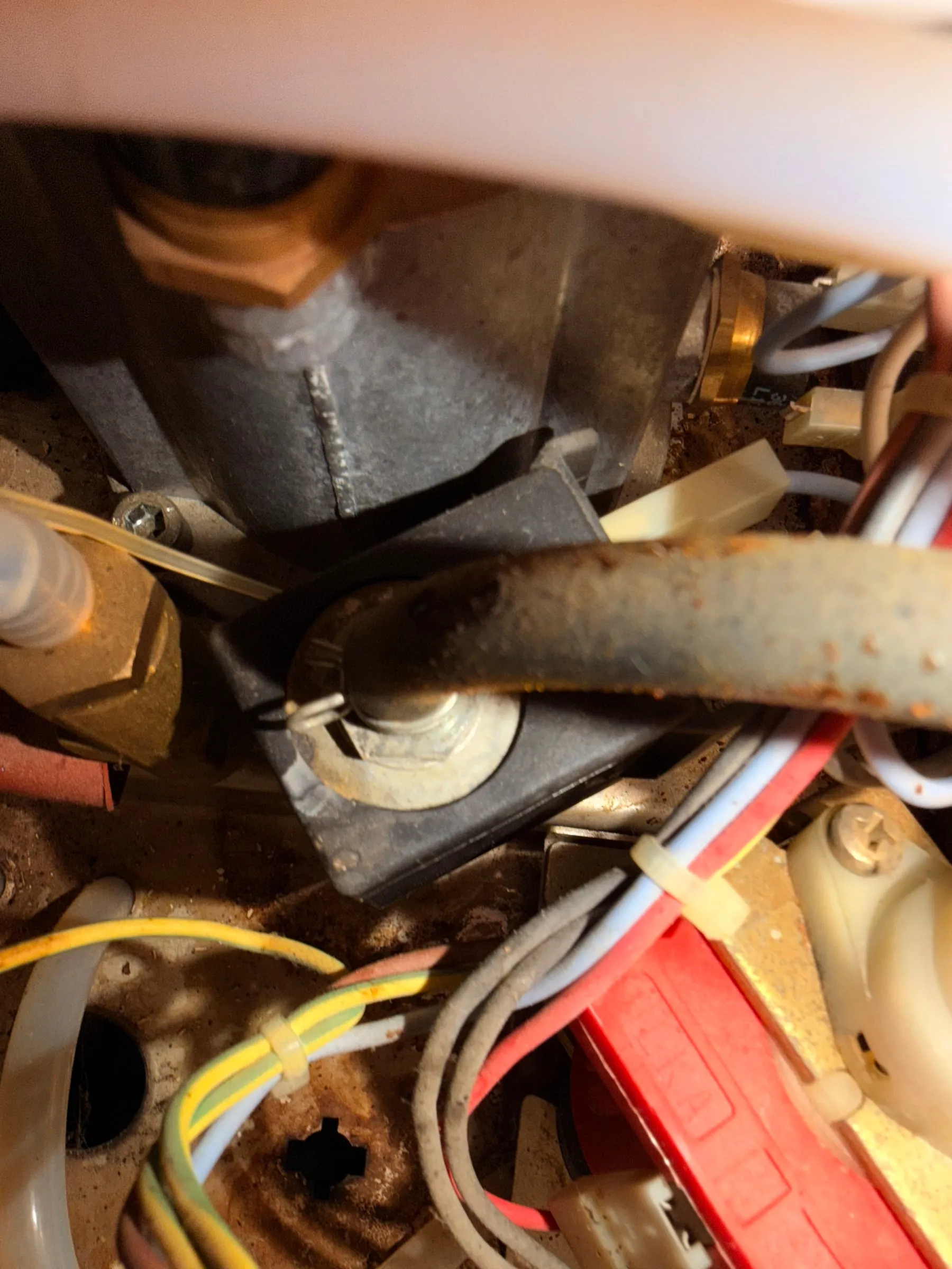
Outside, the stainless front was in decent shape and shiny. Inside, with the base removed, every assembly was complete and original under patina, old coffee, limescale traces and surface rust: the diagonal steel strut distinctly rusty, deposits on the brass and the boiler. A jewel from the front, twenty years of daily use from underneath, and nothing broken, just as described.
Ten minutes with a multimeter
Before ordering a single part I wanted to know whether the expensive things were alive. Four measurements settled it, the most reassuring day of the project in hindsight.
| Check | How | Reading on this machine | Verdict |
|---|---|---|---|
| Heating element | Resistance across each element (the Classic boiler has two) | About 22 Ω per element | Healthy. No open circuit, no short. |
| Earth fault | Each element terminal against the boiler body | Infinite | Insulation fine, no risk of tripping the RCD. |
| Thermostats | Heat in coffee mode until the ready lamp comes on, switch to steam, watch the lamp | Lamp off, machine steams, lamp returns after the reheat | Both bimetal switches behave as designed. |
| Solenoid coil | Resistance across the coil, measured twice | About 1200 Ω | Healthy for a 230 V AC coil. |
Why 22 ohms is a healthy reading
The ballpark came from a video: in The Island Tech's restoration of a scrap Classic, each healthy element reads "around 21 ohms or so". It holds on both sides of the Atlantic, because every Classic has the same two elements of roughly 20 Ω each, wired in series on a 230 V machine and in parallel on a 120 V one. That is why the textbook formula V² / P (explained in this Home-Barista thread) looks wrong at first: it gives the total, 37 to 44 Ω for a 230 V machine and about 10 Ω for a 120 V one, never a single element. Measure each element on its own and expect about 20 Ω.
Electrically this was a clean base, which matters twice: for the restoration and for the controller in Part 2. For the rest of the story, this is how the water travels through a Classic.
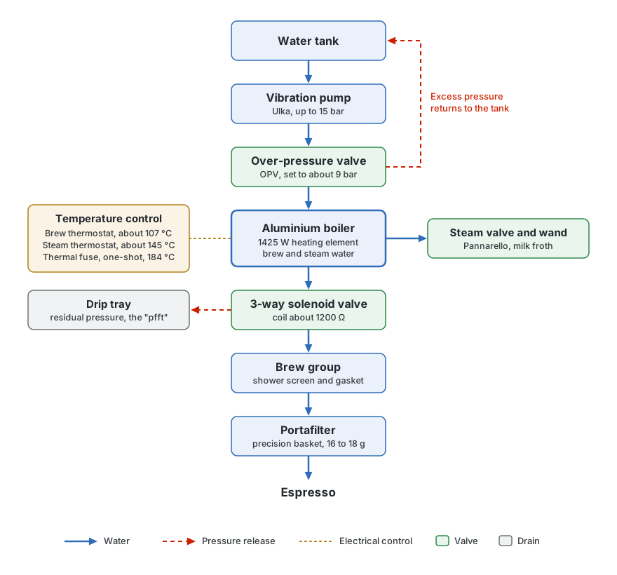
Testing the solenoid valve
The 3-way solenoid valve is what makes a Classic pleasant to use: after a shot it vents the residual pressure from the brew group into the drip tray with a short "pfft", so the puck comes out dry and the portafilter does not fight you. If the valve fails, the portafilter drips and sticks. The usual test, described in this kaffee-netz thread and the KaffeeWiki article on solenoid valves, is acoustic: unplug the pump so its buzz does not drown everything, flip the brew switch and listen. A healthy valve does two things: it clacks when it switches, and then it hums, quietly and steadily, for as long as the switch stays on. I listened for the clack, heard it, and filmed it.
What I did not listen for was the hum. My recording has a clack and then silence. Had I known in July what that silence meant, I would have known the valve was not working, in spite of a healthy coil resistance.
The detour: an audio analysis that proved nothing
In July the result left me more confused than reassured. With the pump connected, its buzz covered everything; with it unplugged I heard a clack every time, but had no reference for a working valve, so I could not tell whether that clack was a pass. An audio analysis on the computer did not settle it either: it found two clicks six milliseconds apart in the clearest example and read them as the switch and the valve armature, but a second, more careful look for this article did not leave much of that standing. Watching the clip today, the missing hum is the most obvious thing in it.
That is what fixed mine: the valve came apart with the over-pressure valve during the teardown, was descaled and cleaned, went back in with new gaskets, and has worked since.
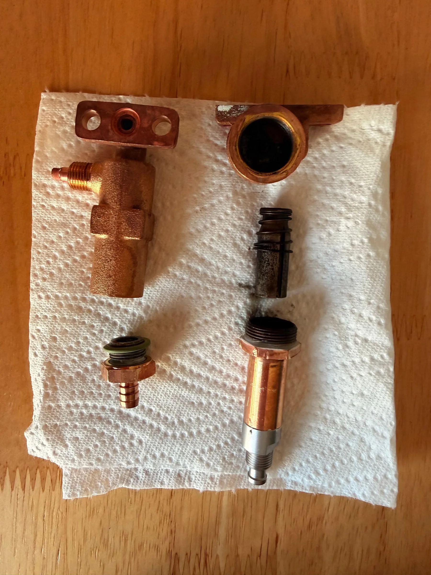
2.Research and the shopping list
I compiled the list once instead of reordering three times: the espresso-specific parts from espressoXXL in one order, most of the chemistry from Amazon, screws and tools from the hardware store. This is what was actually bought and used; two of the tools are on it only because the boiler screws forced them. What it all cost is in the overview: EUR 162 for the espresso-specific parts, chemistry and tools on top.
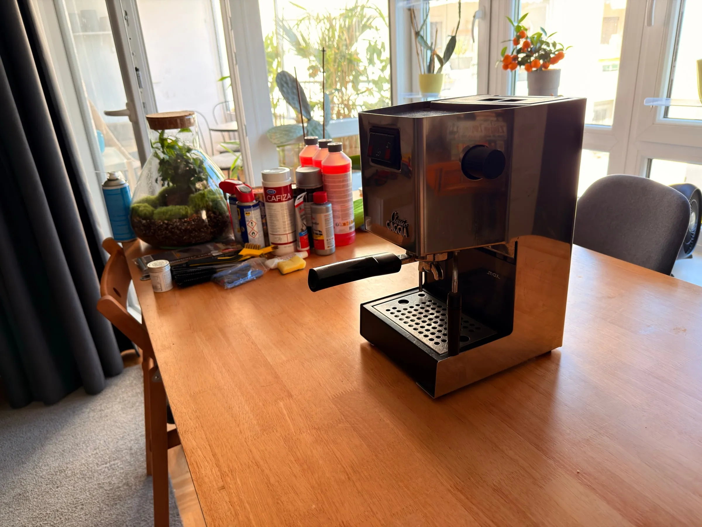
Seals and spare parts
- The maintenance set for the Classic from espressoXXL: the big red boiler O-ring, the blue group gasket, a shower screen with its screw, the small O-rings for the solenoid flange and the steam valve, and a metre of silicone hose
- Two IMS precision baskets, 12 to 18 g, from the same order
- A blind filter, 70 mm, for back-flushing and the pressure test
Cleaning and descaling
- Descaler based on amidosulfonic acid (PURIVITA), safe for the aluminium boiler
- Citric acid for brass and the brew group
- Cafiza for coffee oils. Never on aluminium.
- Bar Keepers Friend for tarnish
- Vinegar and salt, with the citric acid, against verdigris
- A set of long thin brushes, 2 to 25 mm
Rust, paint and polish
- Rust converter (NIGRIN)
- Heat-resistant spray paint, aluminium silver
- Crepe tape and old newspapers for masking
- Autosol metal polish
- Wet sanding paper, 120 to 600 grit
- Two-part epoxy for the tabs that carry the top cover
Grease, paste, sprays and screws
- Food-grade silicone grease (Fermit Glissa, NSF H1) for every seal
- Copper paste for every screw thread
- Contact spray for the spade and switch contacts
- Penetrating oil
- PTFE tape for the pump fitting
- Stainless A2 hex-socket screws from the hardware store for the whole machine, M6 x 16 for the boiler as the parts list says
Tools
- Multimeter
- Hex keys: a long 5 mm one for the boiler screws, a 4 mm one for the group
- Open-ended spanners, 14 and 17 mm, for the valve nuts and the boiler fitting
- Manual impact driver with a 5 mm hex socket, and a hammer
- Hot-air gun
- Digital calliper, bought with the impact driver
- Tape and a pen for the cable labels, a phone for the photos
Bought later, for the epilogue
- An Ulka EX5 pump with a brass outlet
- A shower holder in brass; the aluminium original is no longer available
- A rubber pump mount
- A portafilter pressure gauge, 0 to 16 bar
- A second group gasket and O-ring that turned out not to be needed
What I did not buy: thermostats (Part 2 replaces them anyway), a clear coat for the housing (it yellows at the hot group), a new boiler, and a new solenoid valve. The diagnosis pointed at cleaning, not replacing.
Taking it apart
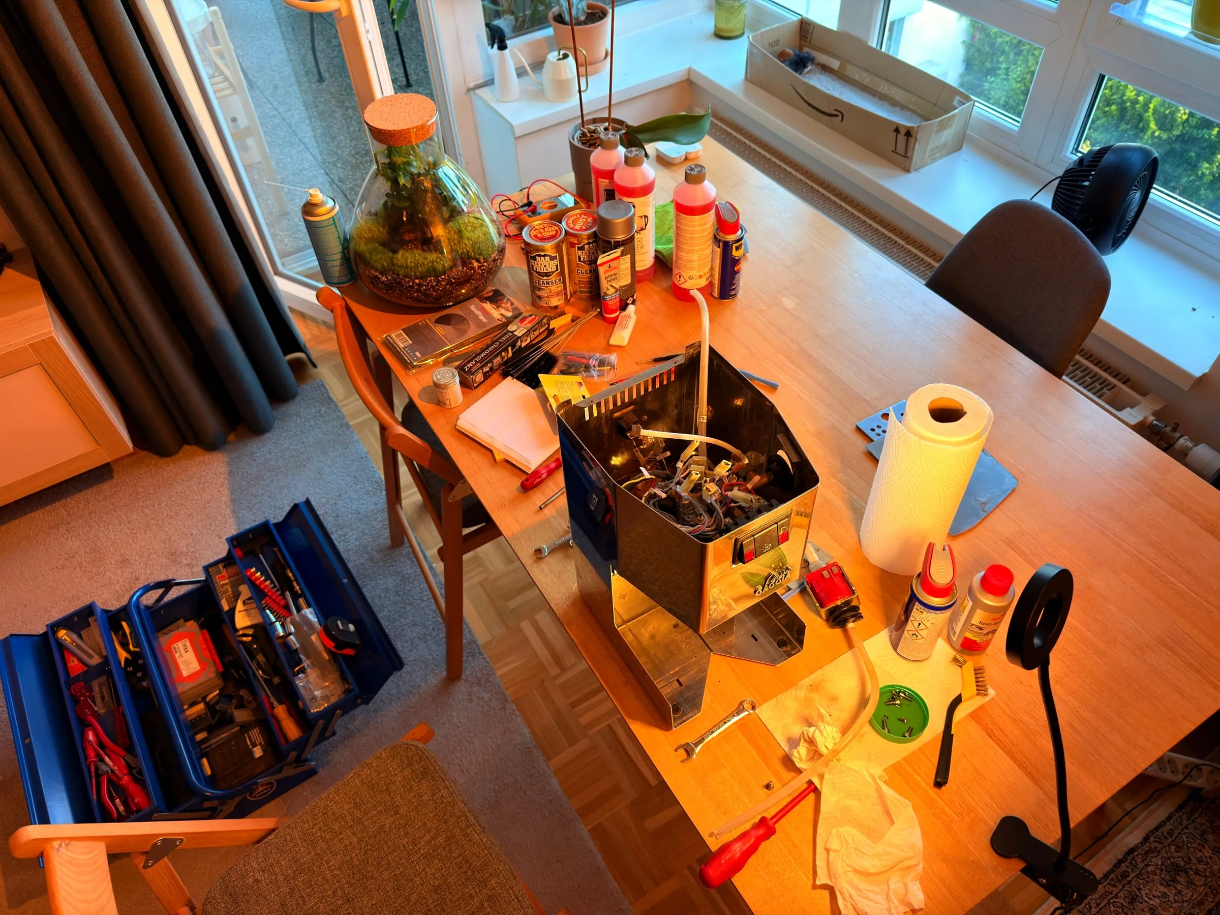
3.Teardown: label everything
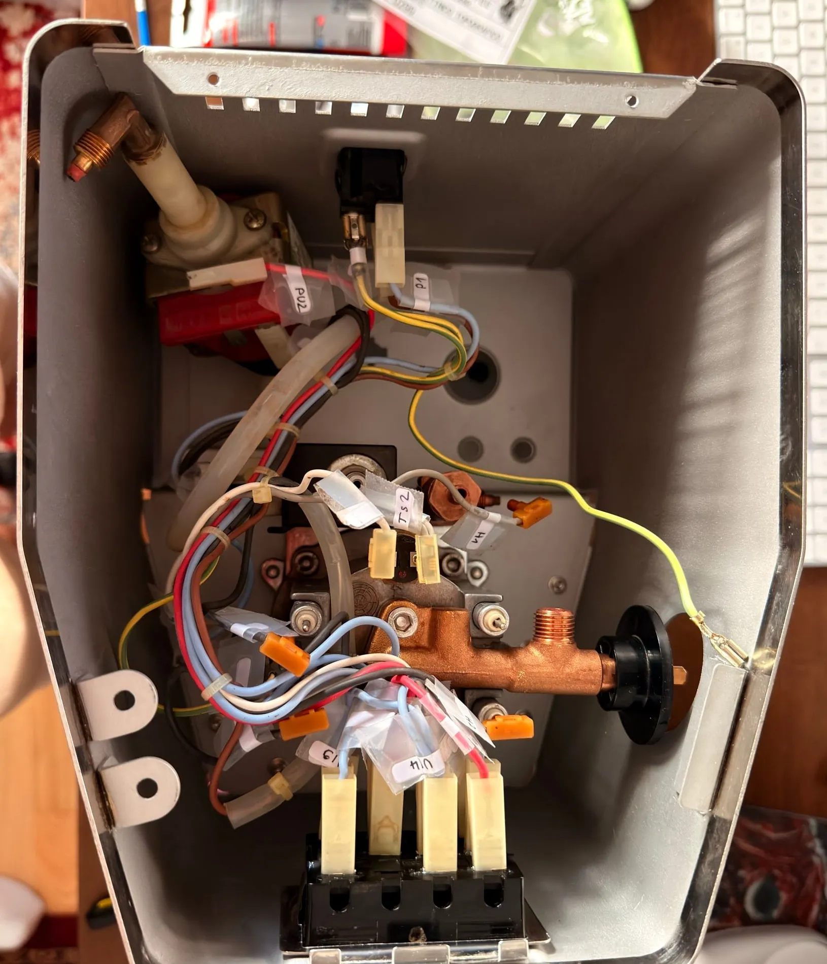
On 17 July the machine came apart: housing open, wiring released, every cable labelled with a strip of tape before it was unplugged, H1 to H4 for the heater, PU1 and PU2 for the pump, TS1 and TS2 for the thermostats, and so on. Roughly 60 photos, one per step. Six weeks later that discipline was the difference between reassembly and guesswork.
For the order screw by screw, The Island Tech's restoration of a scrap Classic was my blueprint; I watched it many times, and the Whole Latte Love boiler video covers the boiler itself. Both are better than any text. The short version I followed: plug out, tank empty, drip tray and grid off, housing off. The switch block at the front comes out first, because it stands in the way of everything else; then the wiring, cable by cable, each one labelled before it is pulled; then pump, valves and the boiler with the group come out as one unit, hoses still attached, and only come apart on the bench. Two things to note on the way: where the thermal fuse sits on the boiler, a one-shot fuse in a small bracket that has to go back exactly there, and which screw came from where, because they are not all the same length.
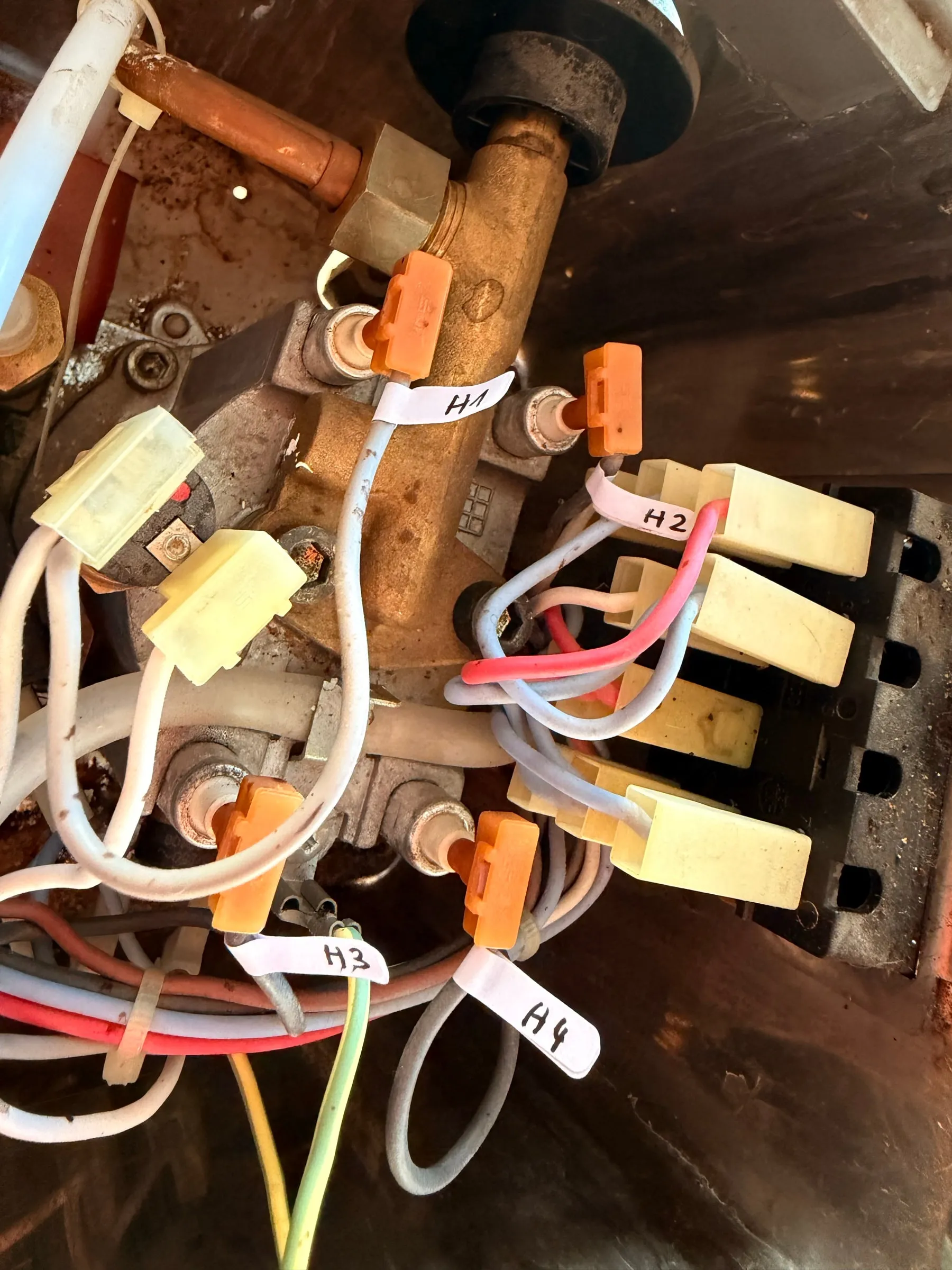
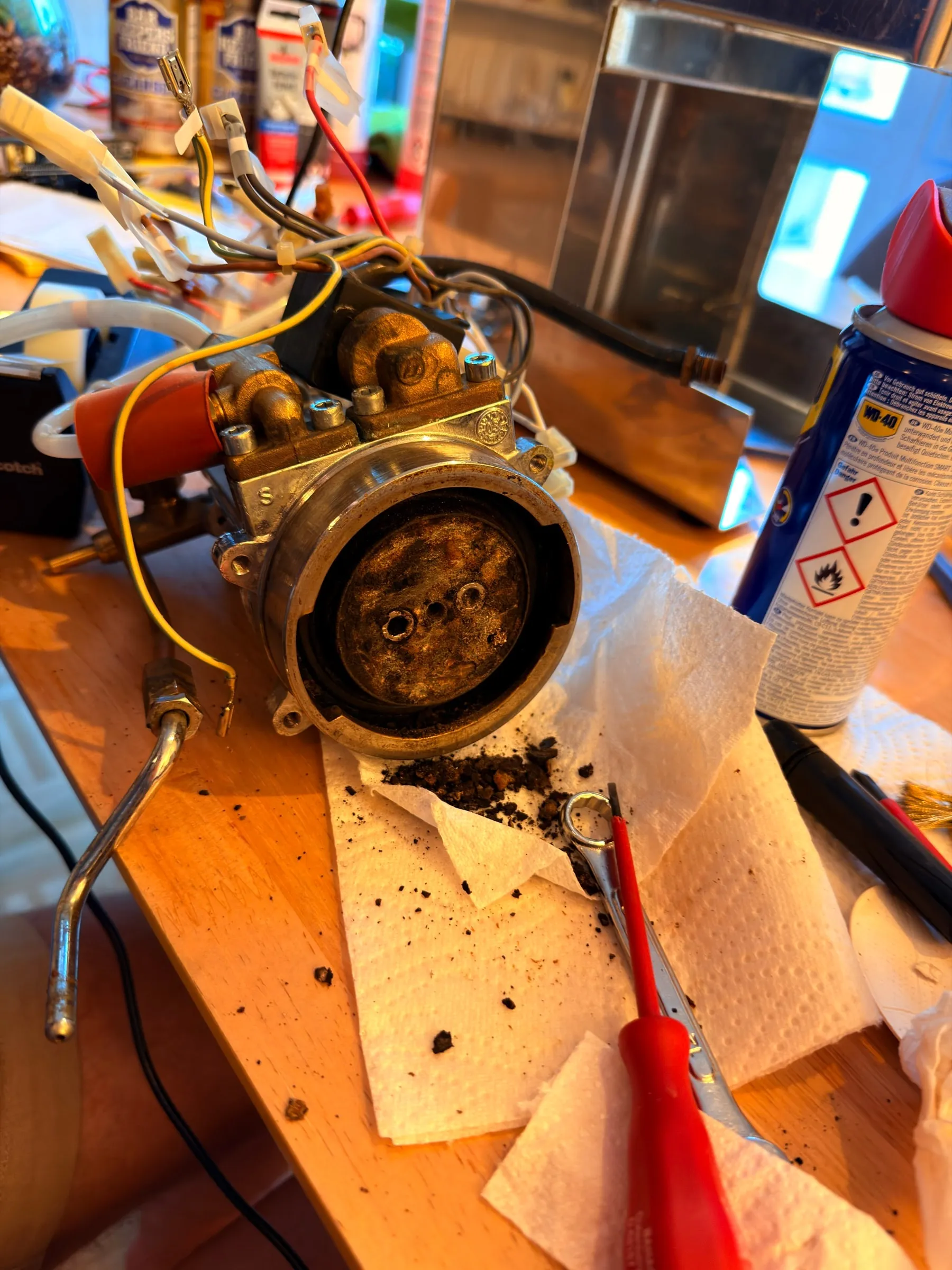
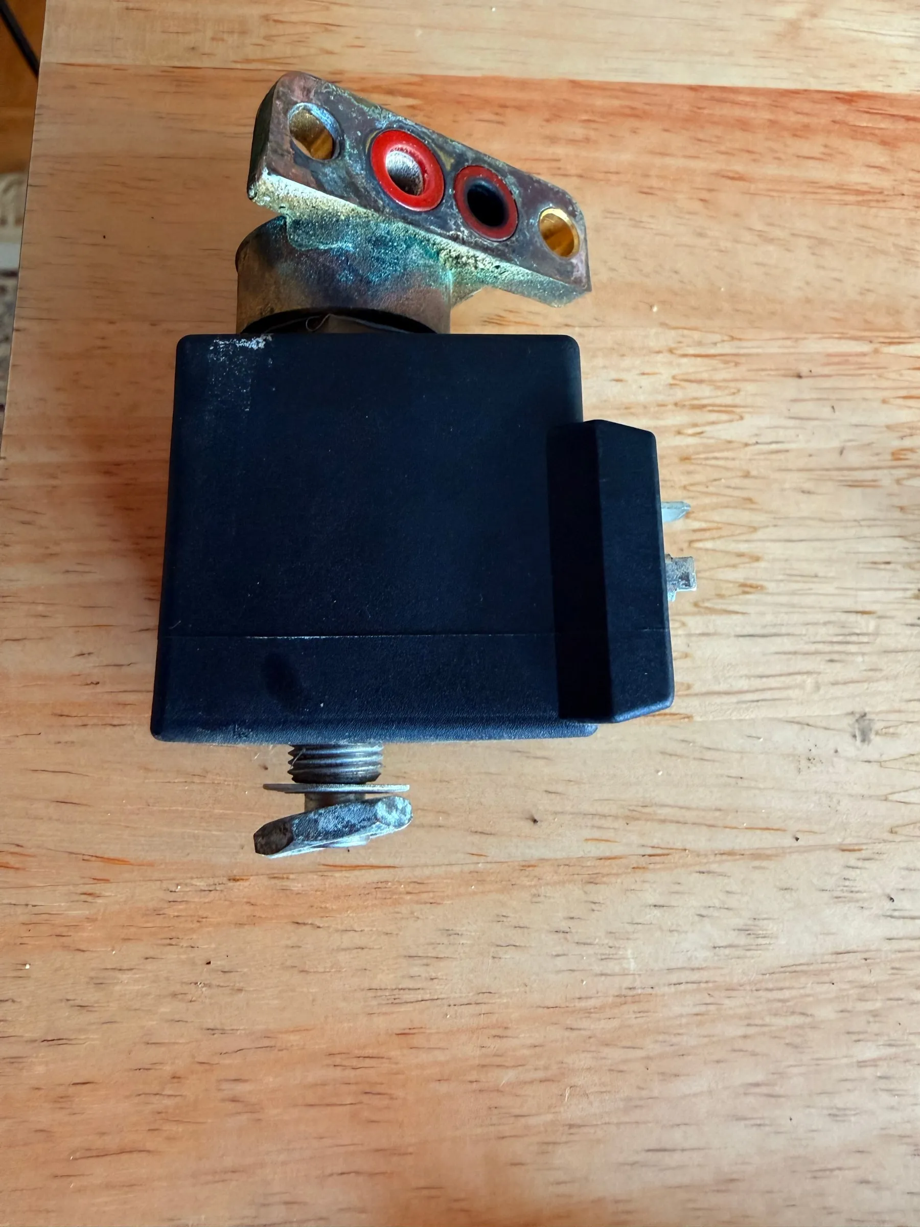
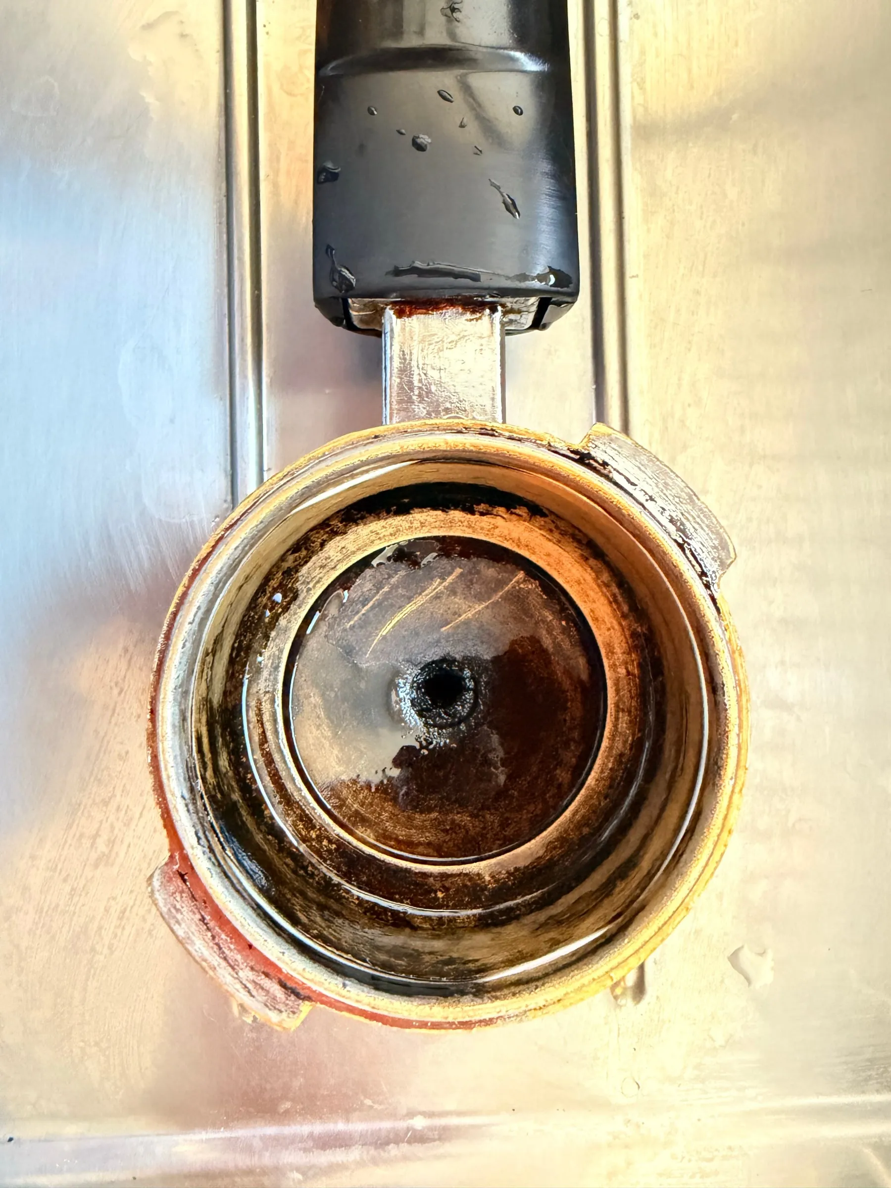
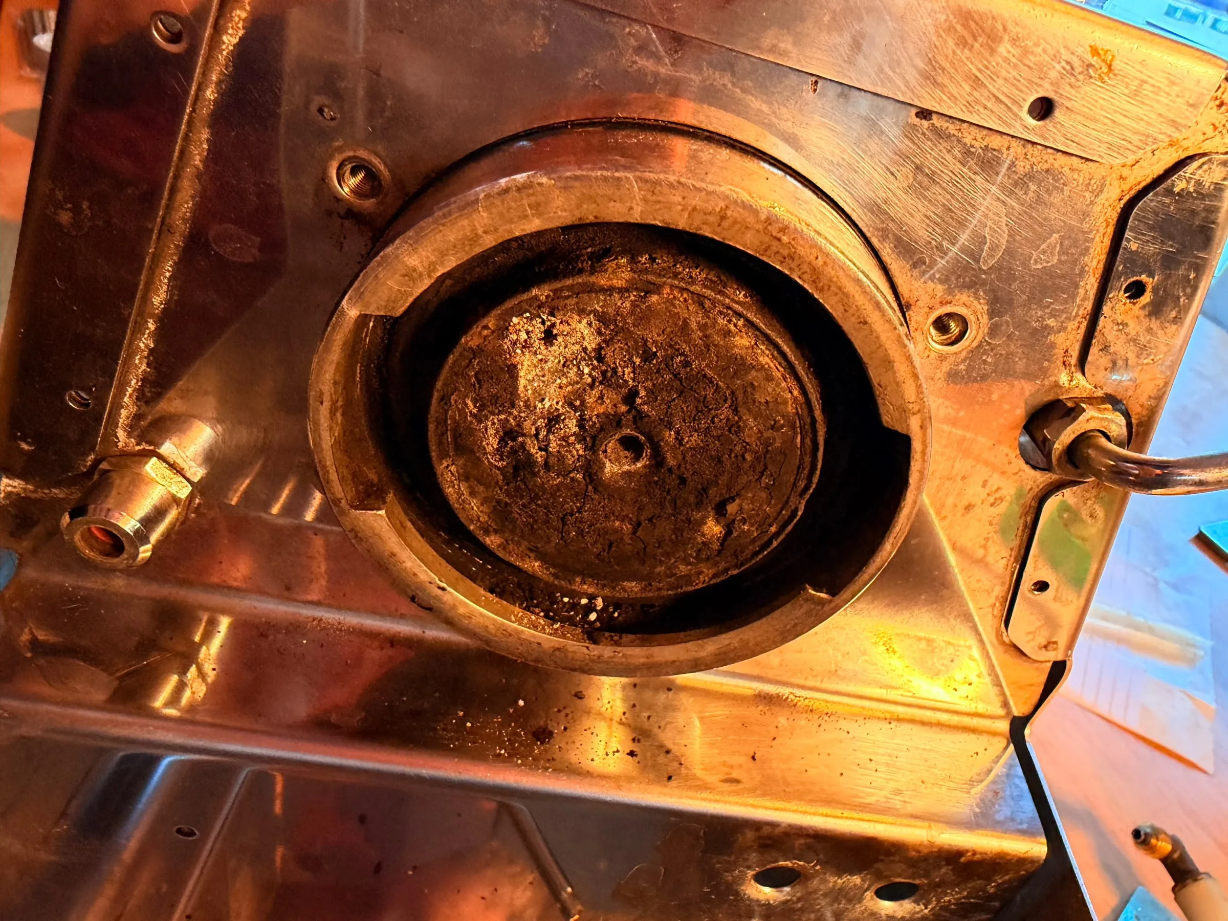
Up close, nothing was broken, but every surface that touches water or coffee had a layer on it: baked coffee behind the shower screen, scale on the sealing faces and around every port, verdigris where brass met aluminium, every gasket baked onto its flange, and a small heap of debris that fell out of the assembly onto the kitchen paper.
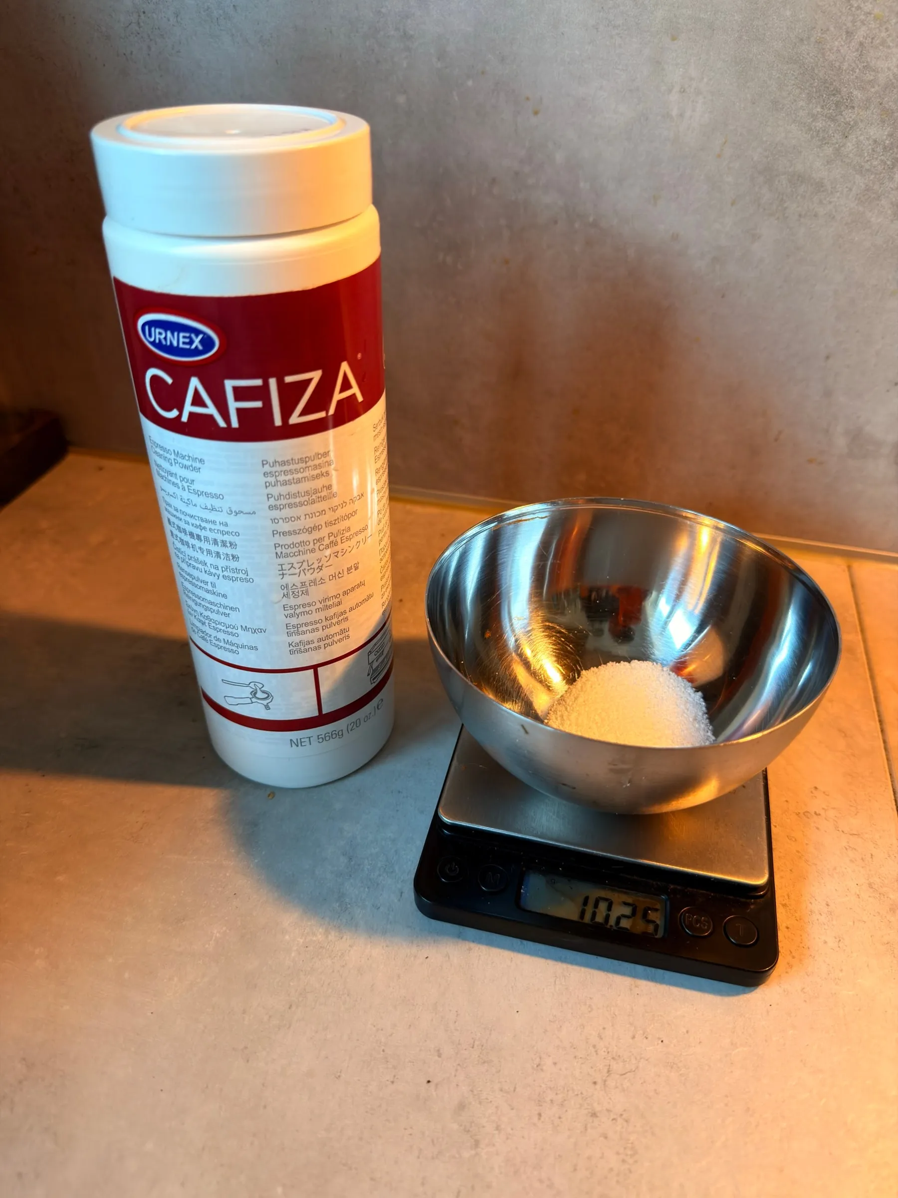
The portafilter went into a Cafiza bath several times, 10 g in 1.5 litres of hot water each time.
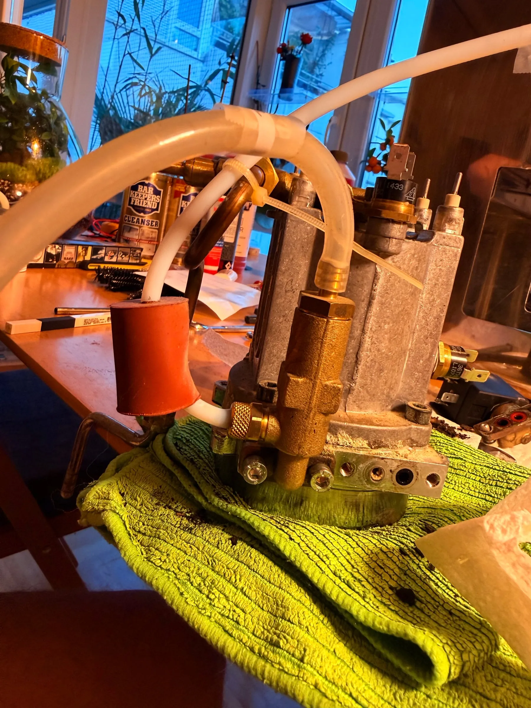
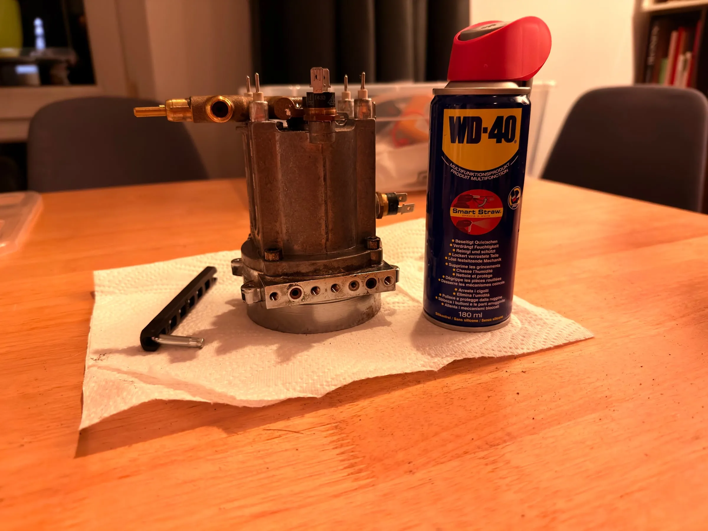
The boiler came out with the brew group, coated in patina and limescale, and stayed shut: its screws were seized.
4.The boiler that would not open
Four M6 x 16 screws hold the two halves of the boiler together: the aluminium casting with the two heating elements above, the group body below, the big red O-ring between them. On my machine they had not moved in twenty years. Steel in an aluminium thread, heated every day and occasionally damp, corrodes into it until screw and boiler behave like one part.
Round one, on the evening of the 17th, was the long 5 mm hex key. Nothing moved. I could feel the key twist before the screw did, and that is the moment to stop: a rounded hex or a sheared screw turns a free evening into the search for a new boiler. So the boiler got a soak in penetrating oil and a night on the kitchen table. Round two, the next morning: more oil, the same key, the same result.
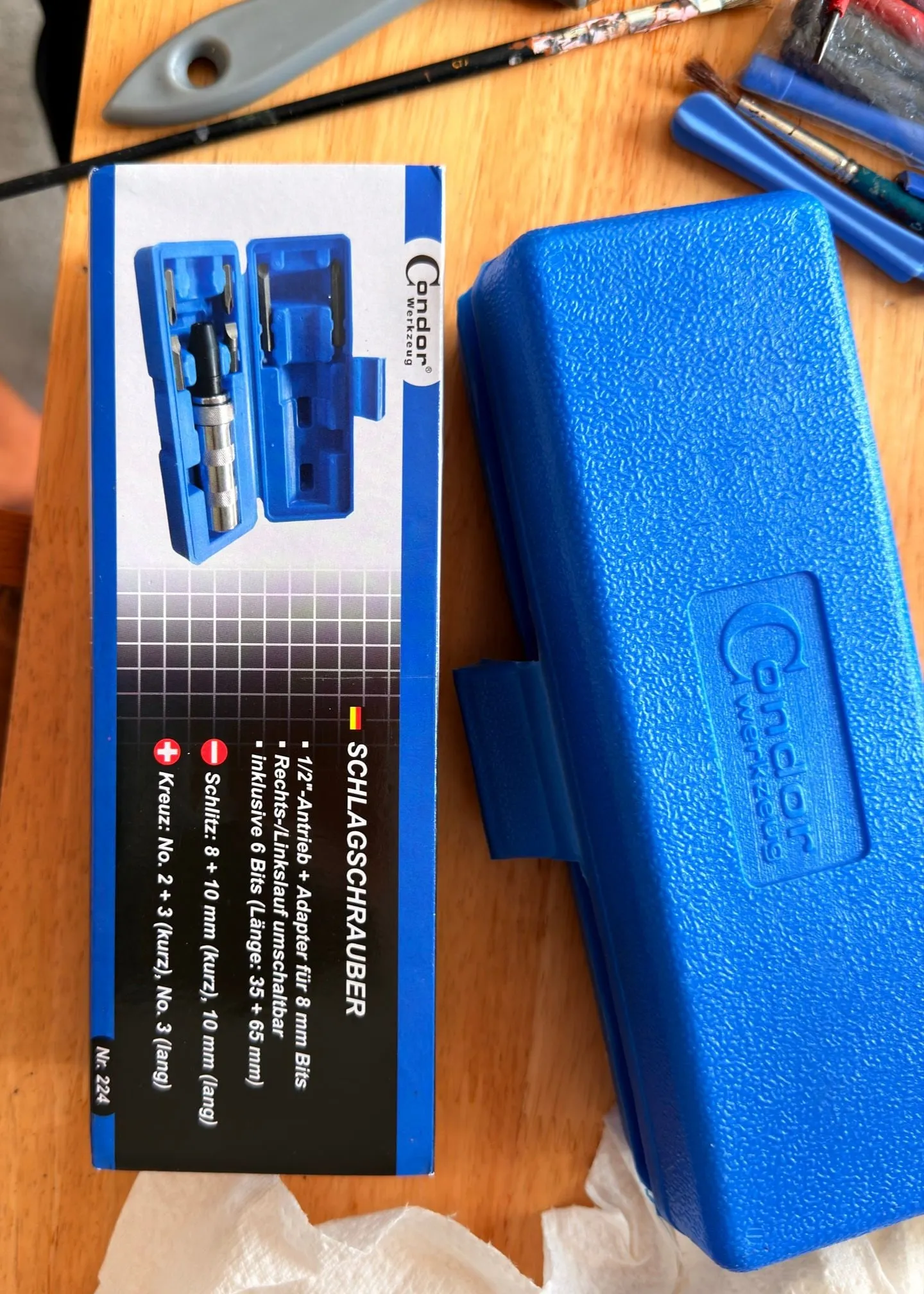
Round three started at the hardware store. The tool for this job is a manual impact driver: a heavy steel cylinder that you load with a bit, set against the screw and hit with a hammer. The blow drives the bit deep into the screw head, so it cannot slip and round the hex, and a cam inside turns the same blow into a short, violent twist. It needed a proper 5 mm hex socket, because the bits in the box are for slotted and Phillips screws.
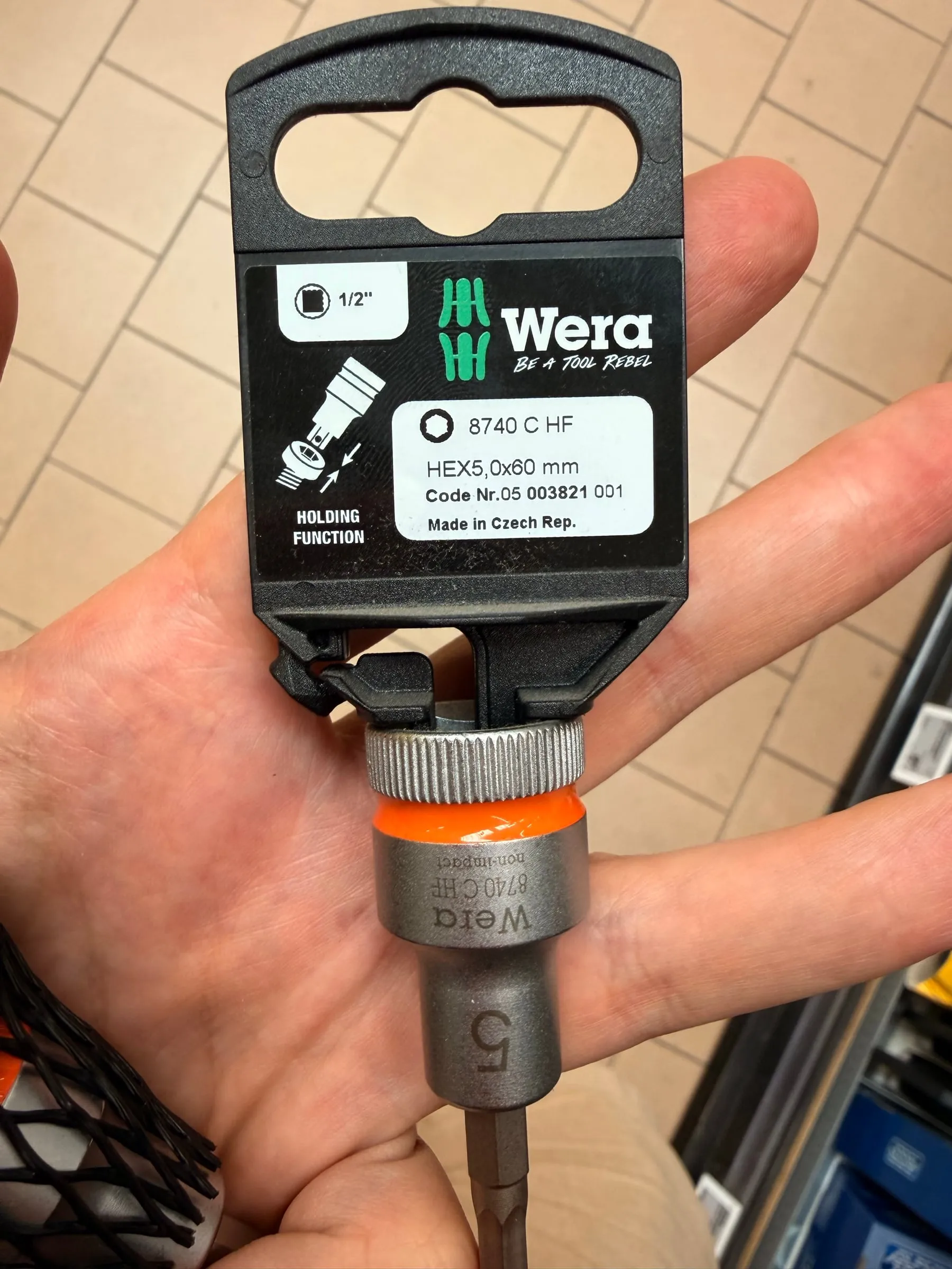
The last ingredient was heat. Aluminium expands about twice as much as steel, so a hot-air gun on the boiler body around each screw opens the thread by a hair and weakens the corrosion bond. Even so, none of the four gave up easily: heat, set the driver, hit hard, check, heat again, hit again, many times over before a screw moved for the first time. Around four in the afternoon, the better part of a day after the first attempt, the last one let go.
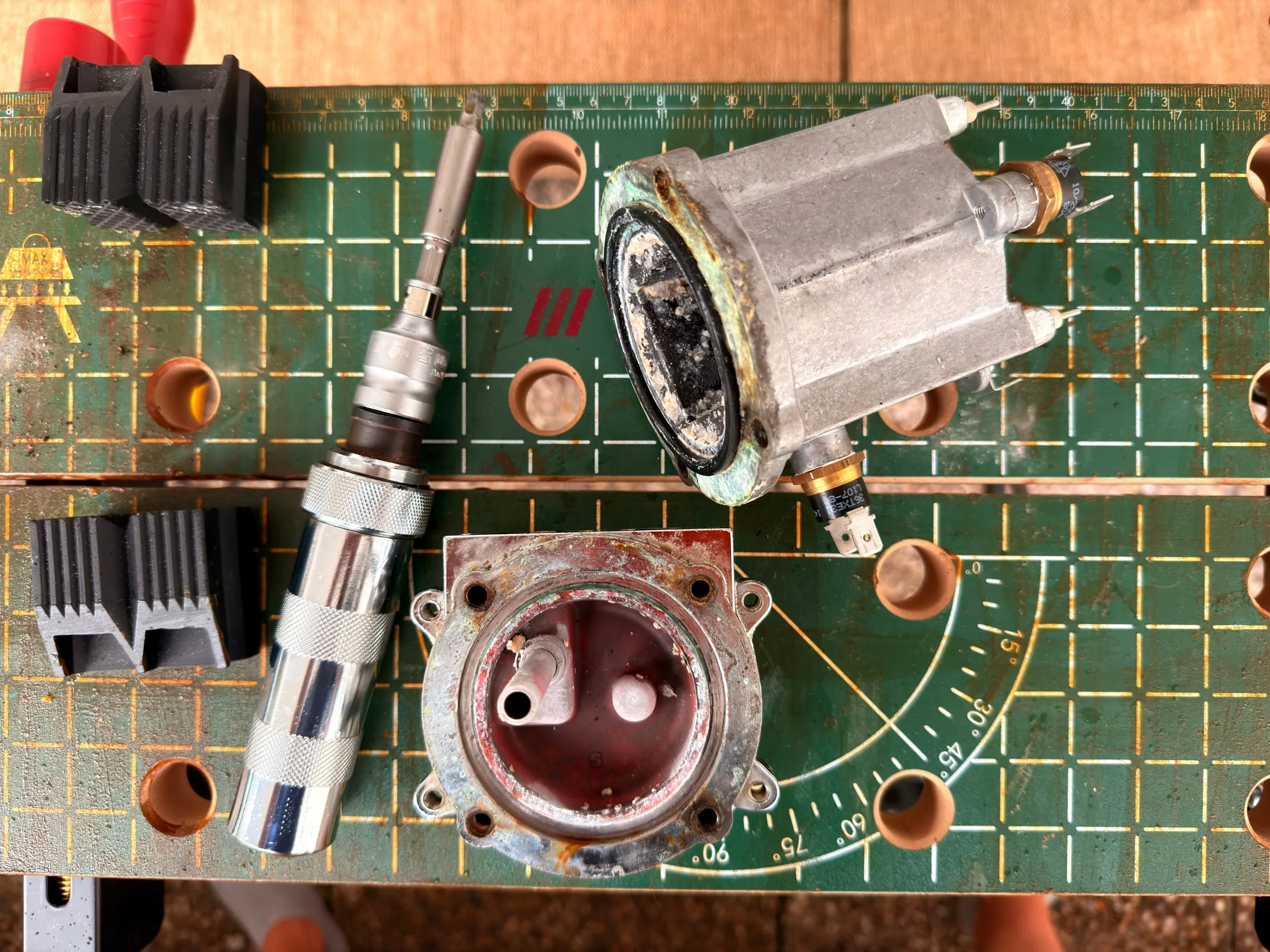
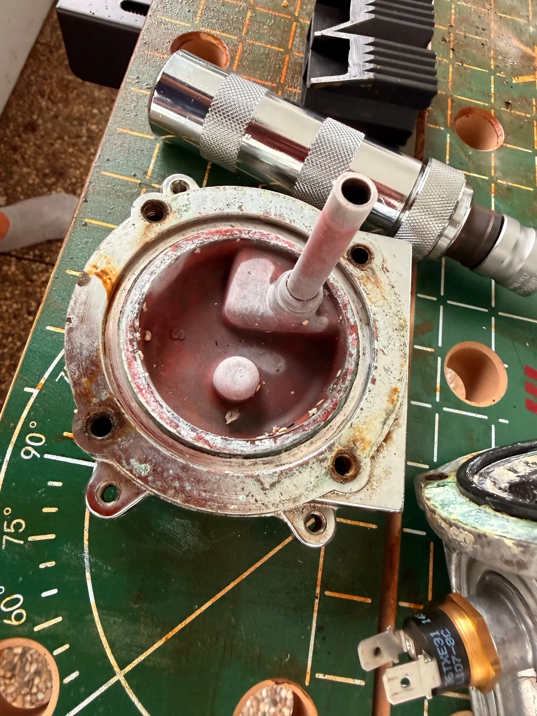
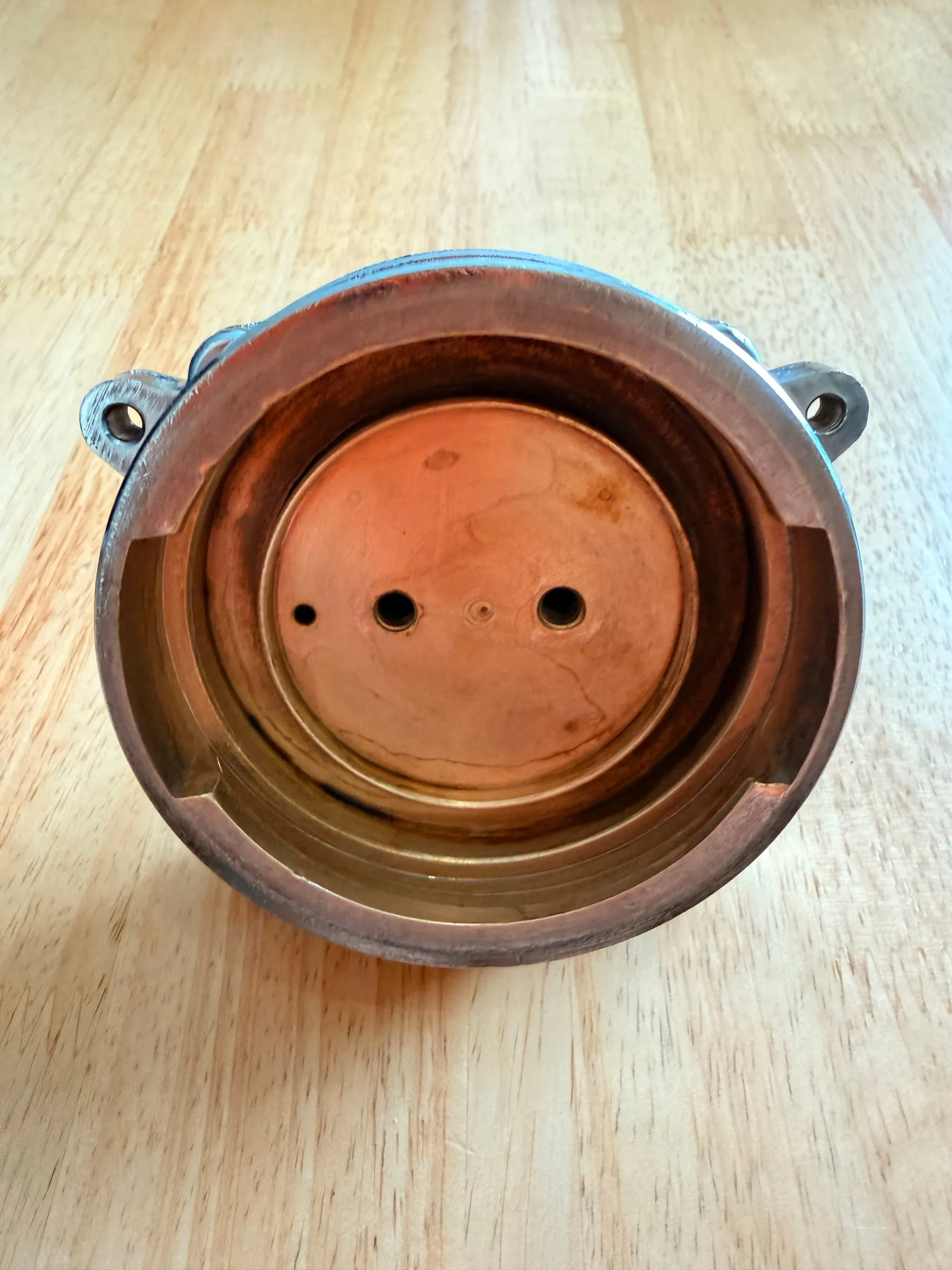
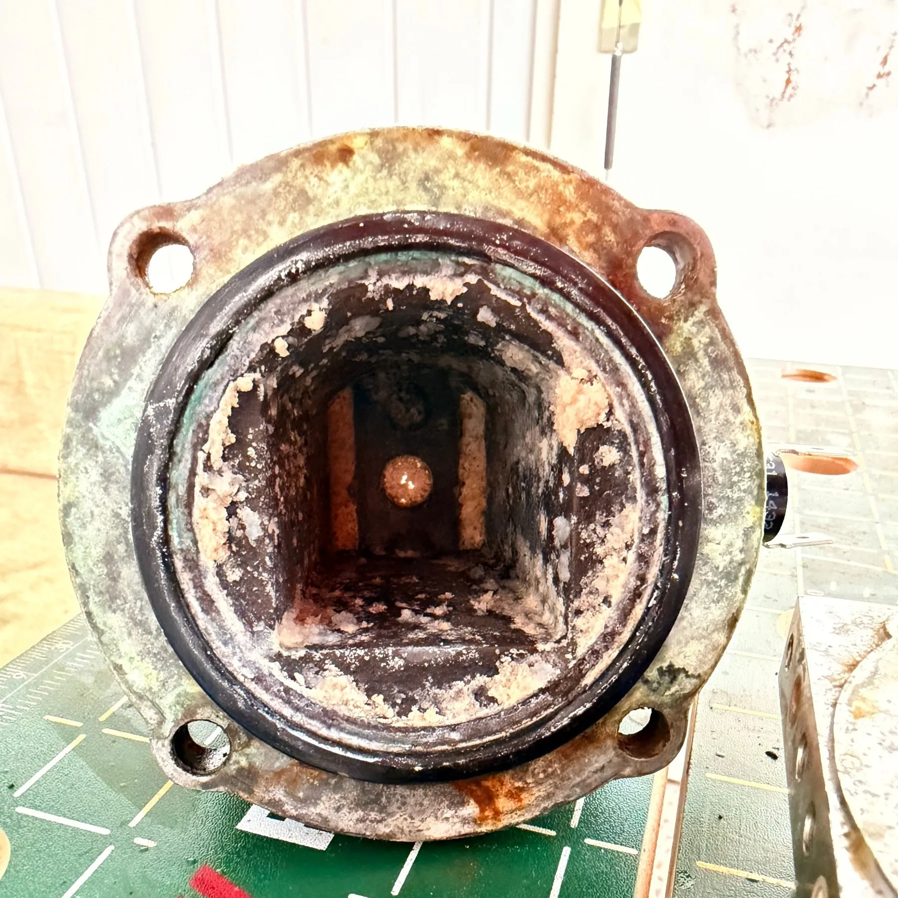
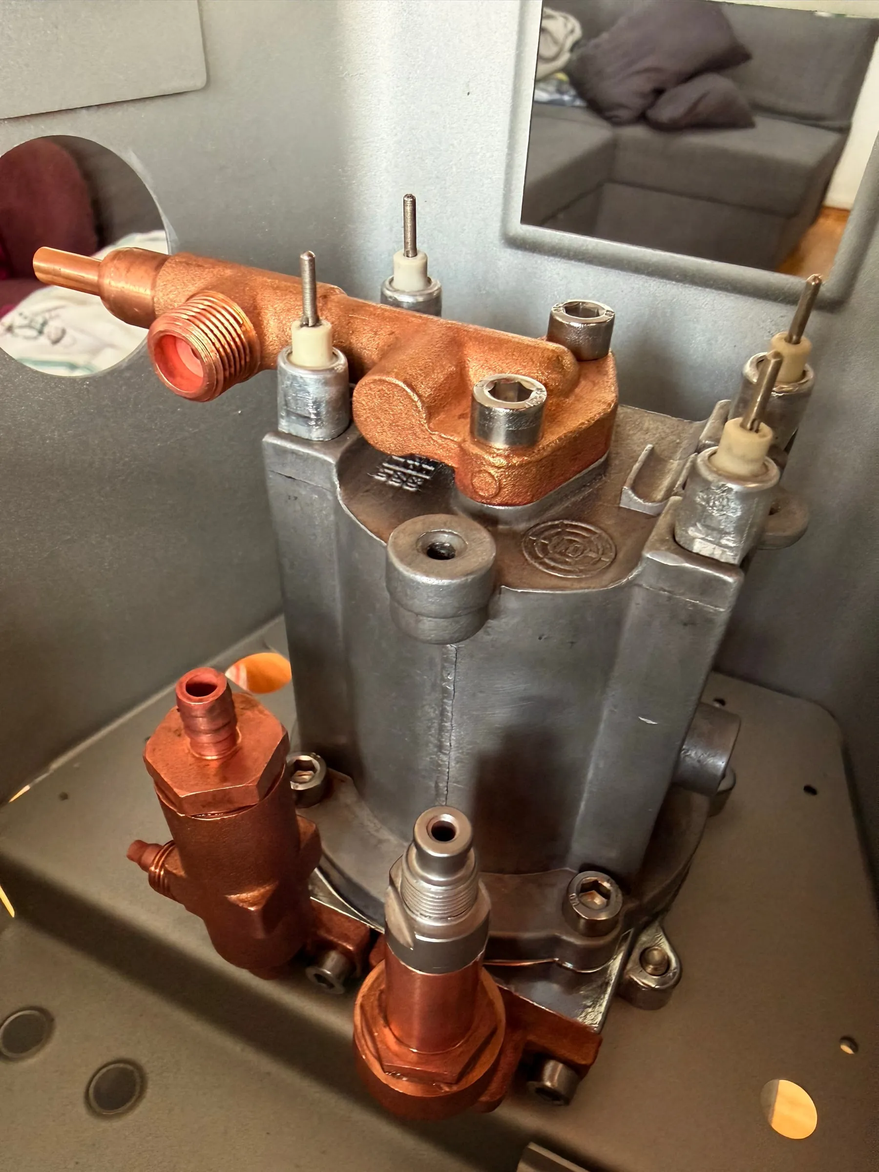
Inside it looked like a twenty-year-old kettle: a crust of scale in the upper half, deposits around every opening, a gasket baked hard. This is also the moment to decide whether the boiler stays. Scale and shallow marks on the sealing face are cleaning and lapping work. Deep pitting in the face or in the cavity is not: a new seal will not hold on it, and the boiler needs replacing. Mine had scale, a baked gasket and no pitting, so it stayed.
Cleaning, rust and paint
5.Rust, descaling and polishing
Rust: convert, don't grind
The rust was what made the machine look old more than anything else. The steel base plate around the pump and boiler mount had a proper bloom of orange flash rust but no perforation, exactly the case a rust converter is made for: applied straight onto the firmly adhering rust, not down to bare metal, no neutralising afterwards, self-priming. The small steel brackets and screws got the same treatment in the lid of a storage box.
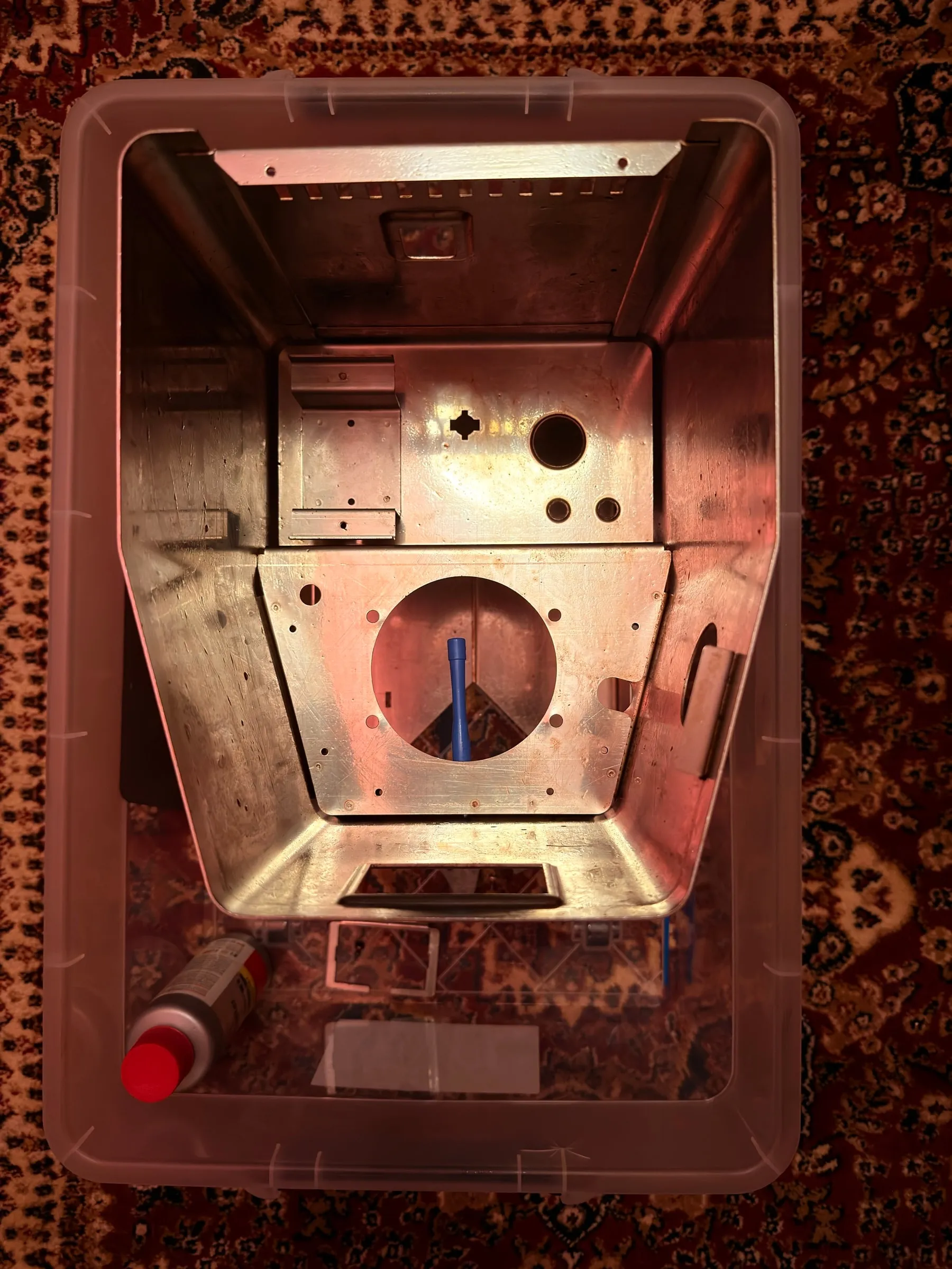
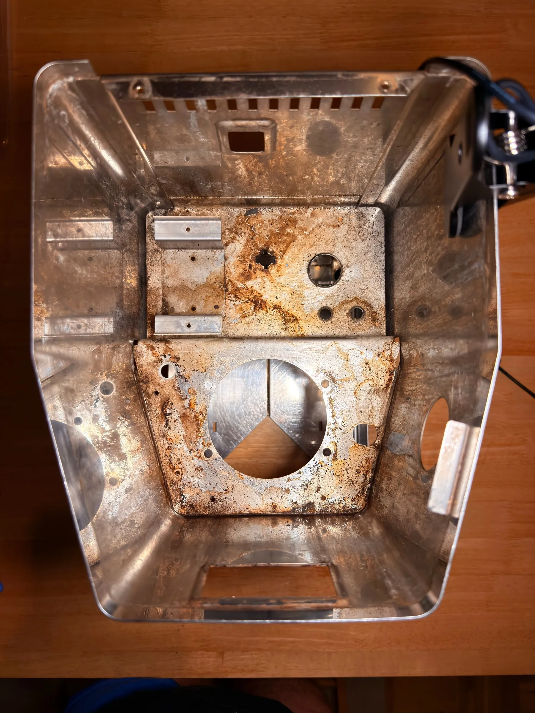
Only surface rust, no rust-through, so the chemical route instead of grinding was the ideal case.
Descaling and polishing
With the boiler open, everything that carries water went into the descaler: the boiler casting, the group body, the valves and the lines. PURIVITA is an amidosulfonic acid descaler, safe on aluminium, with a colour indicator that turns from red to yellow as the acid is used up. I used it at the dilution on the bottle, in several short rounds with a rinse and a look in between rather than one long soak, because the acid does not stop when the scale is gone. Any seal you mean to reuse comes off before the bath; acid hardens rubber. Mine were all being replaced anyway.
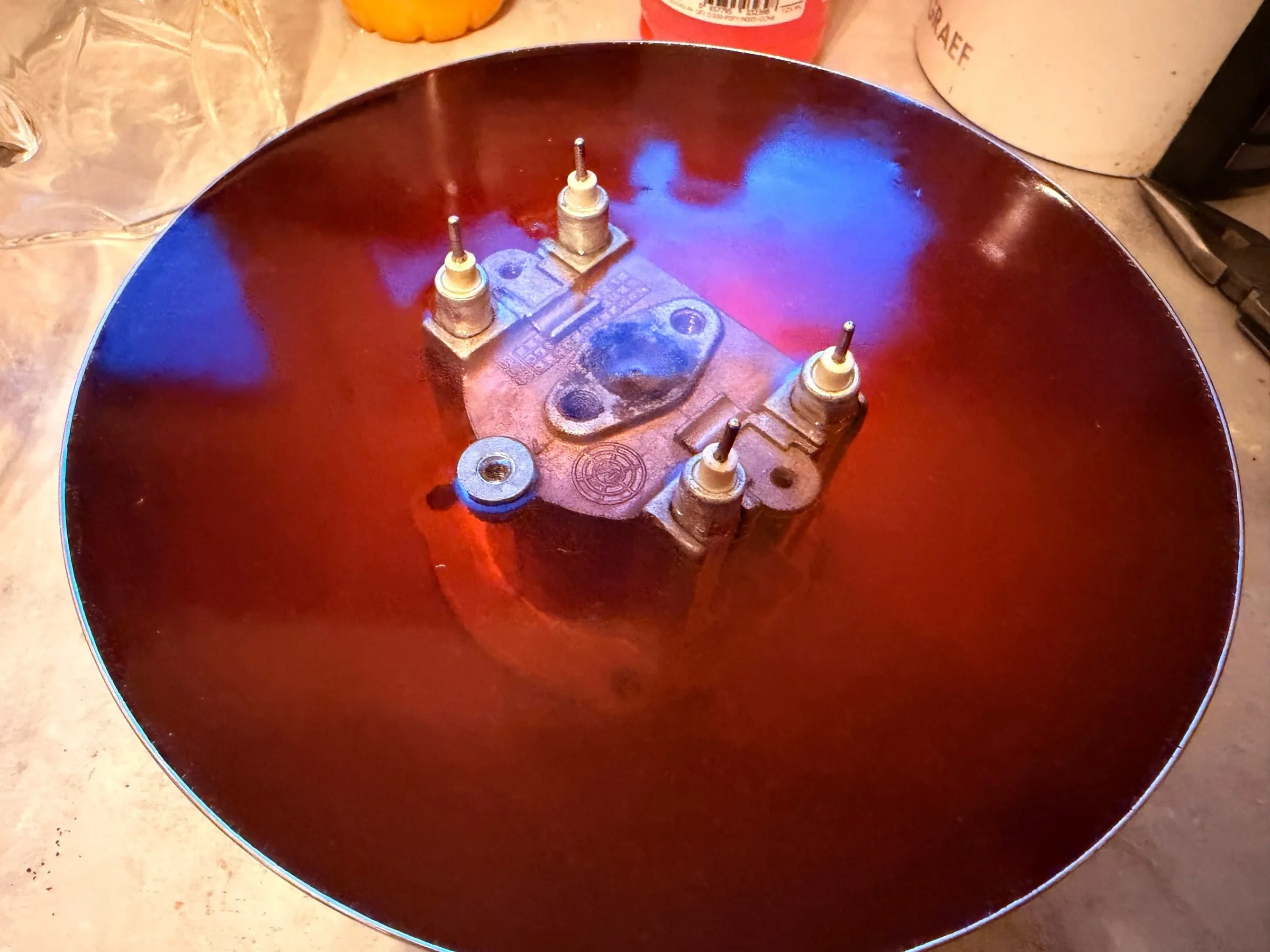
The brass parts, valves and water lines came out of the same baths clean and matt; the brew group got an extra round of Cafiza for coffee oils and Bar Keepers Friend for the tarnish. The rest of the day went into the housing: cleaned completely and polished mirror-bright, inside and out, rust-free. That is the moment a machine stops looking like scrap and starts looking like a project.
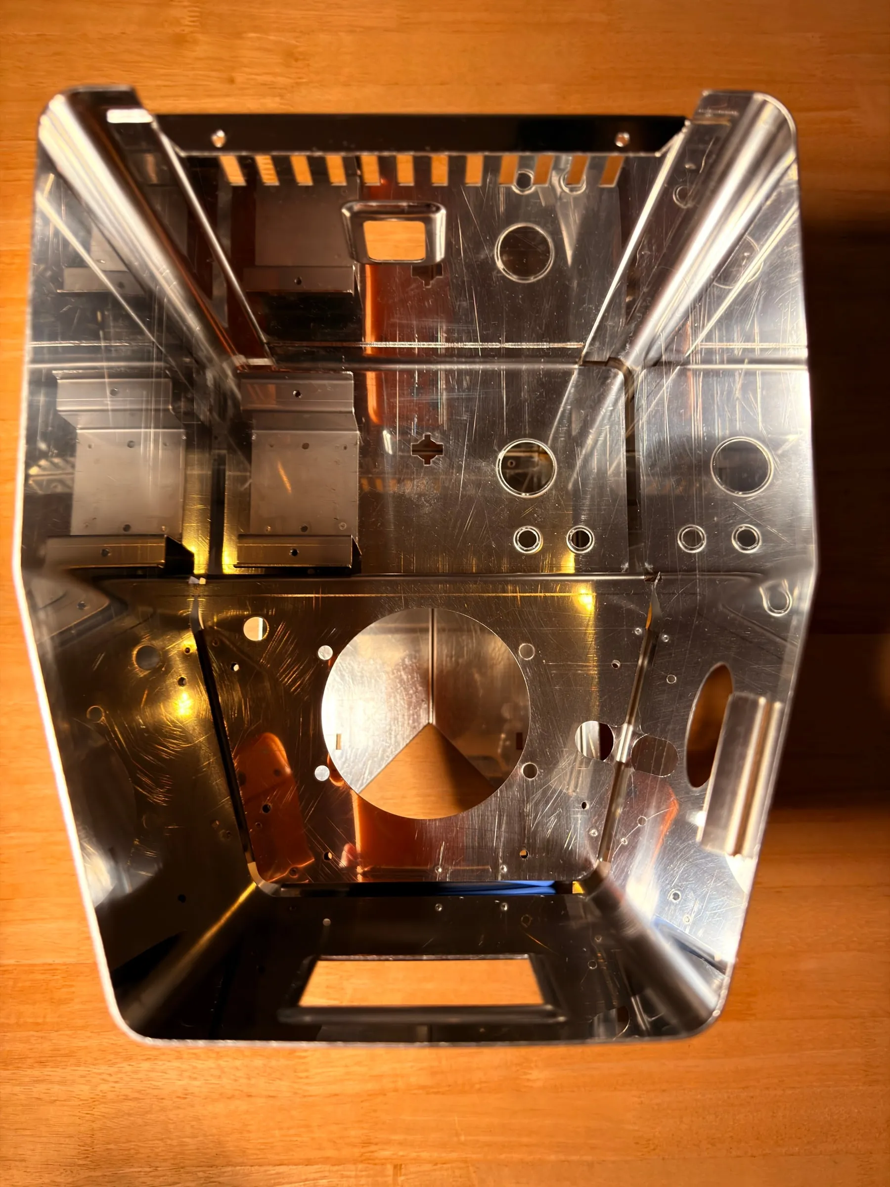
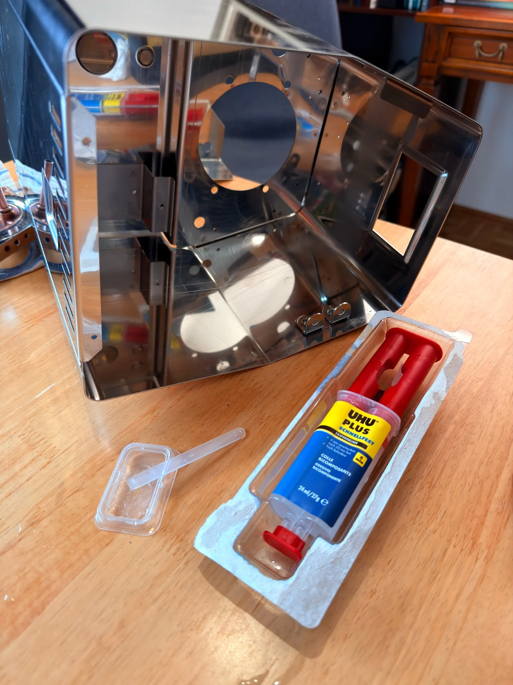
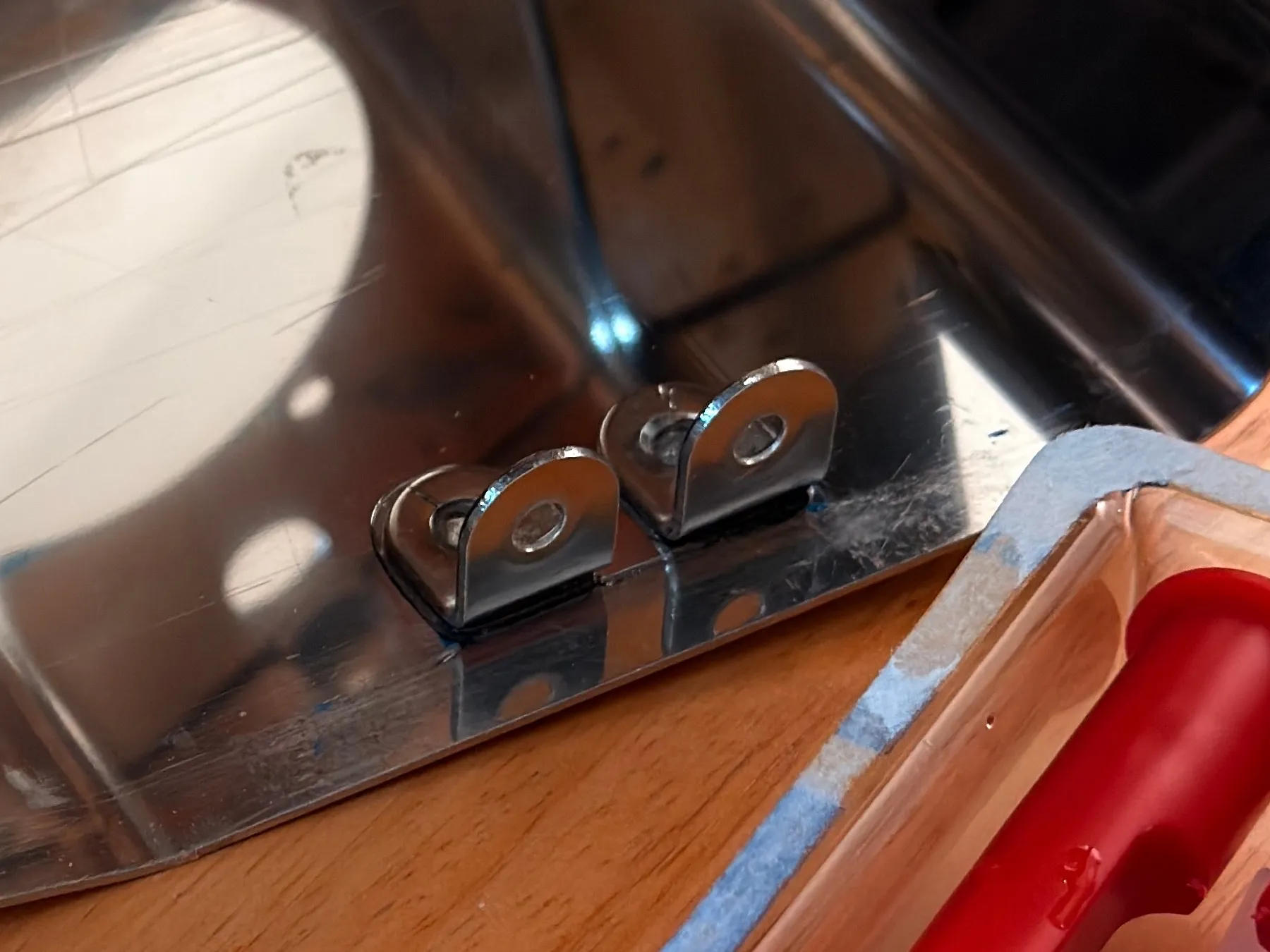
The housing also got a repair the factory owed it. The top cover, the cup tray, rests on small steel tabs glued to the inside of the housing, and on one side they had never been fitted, so the cover sagged there. On the evening of the 18th I glued them in with two-part epoxy, the faces sanded and degreased first. The glue is rated to about 100 to 120 °C, which mattered a few days later at the oven.
6.Fine cleaning: citric acid and verdigris
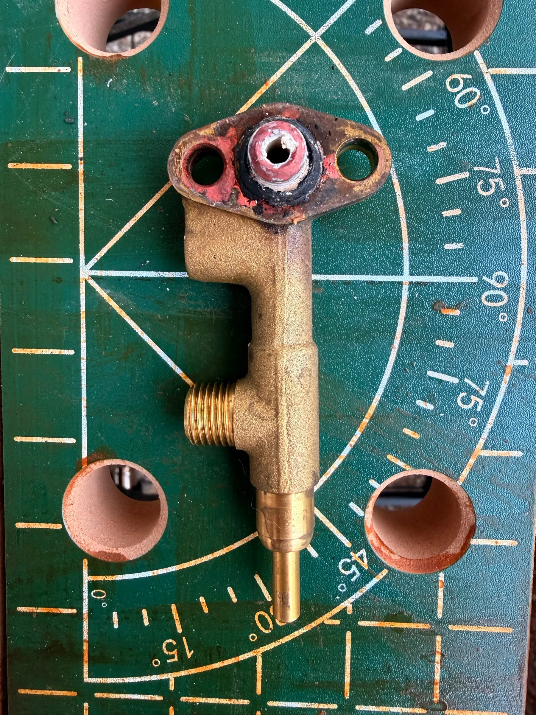
The 19th was fine cleaning. The inside of the brew group had gone dark from the alkaline Cafiza baths and brightened up again in warm citric acid, 30 to 50 grams per litre at 40 to 60 °C, never boiling, or calcium citrate precipitates as a new deposit. The rule I learned that day: degreaser first, acid last, or it tarnishes straight away again.
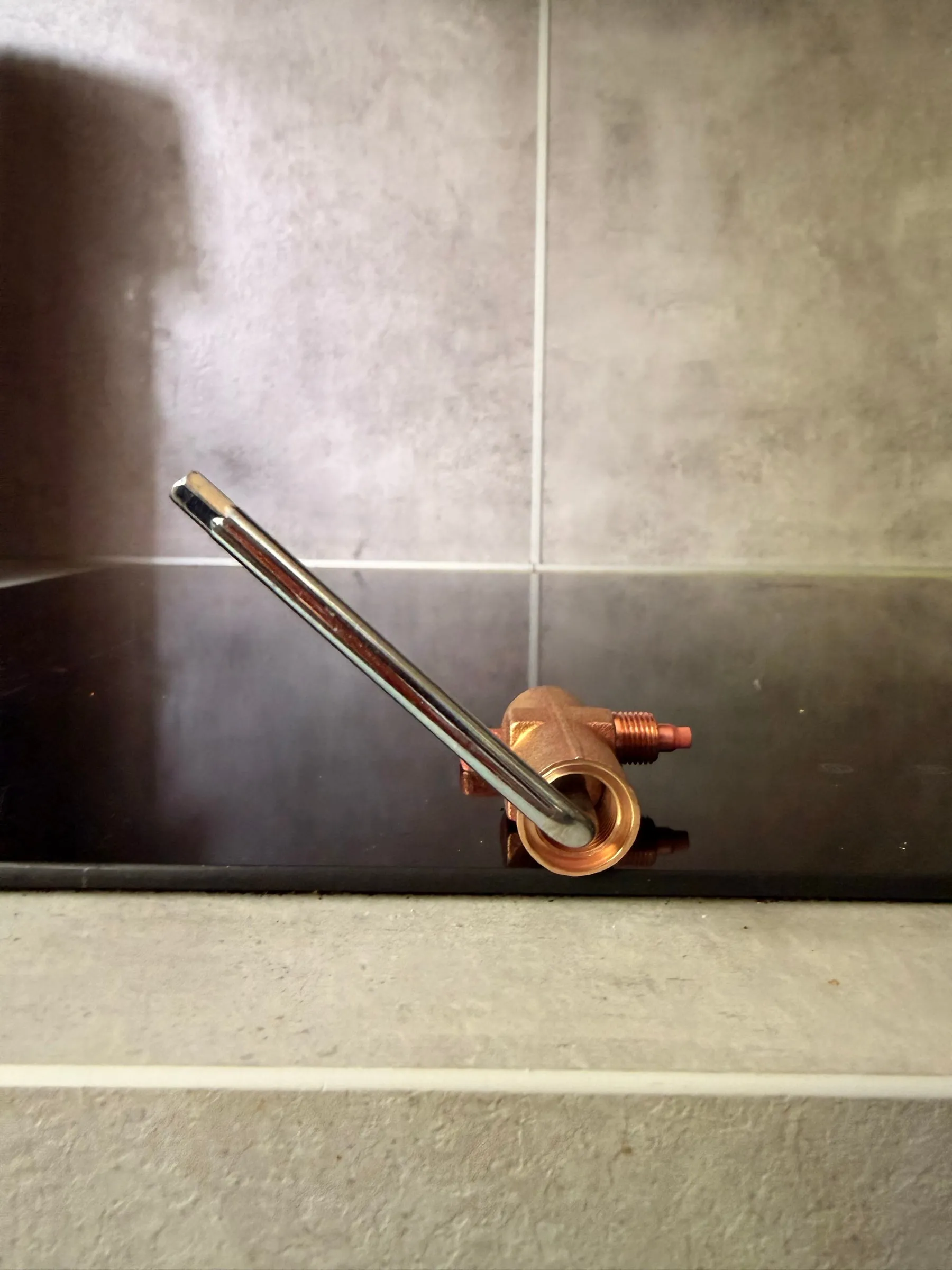
The same day I took the over-pressure valve and the solenoid apart, and got a fright: was there a spring in the OPV, and had it jumped out and rolled under the workbench? After some reading, relief. The spring sits captive behind an internal 5 mm hex adjuster, which is also the brew-pressure setting, and had never been out.
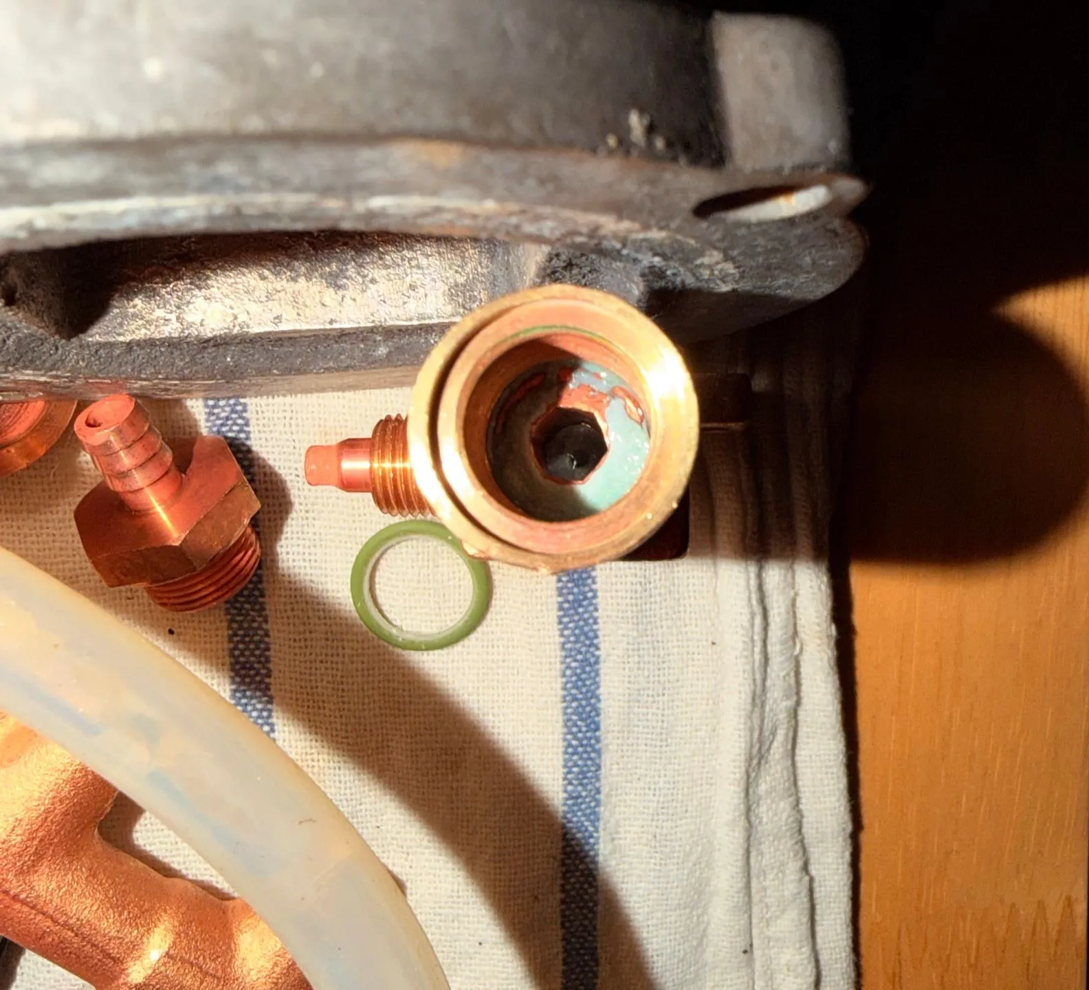
The exploded drawing settled it, and the adjuster turned out to matter again below.
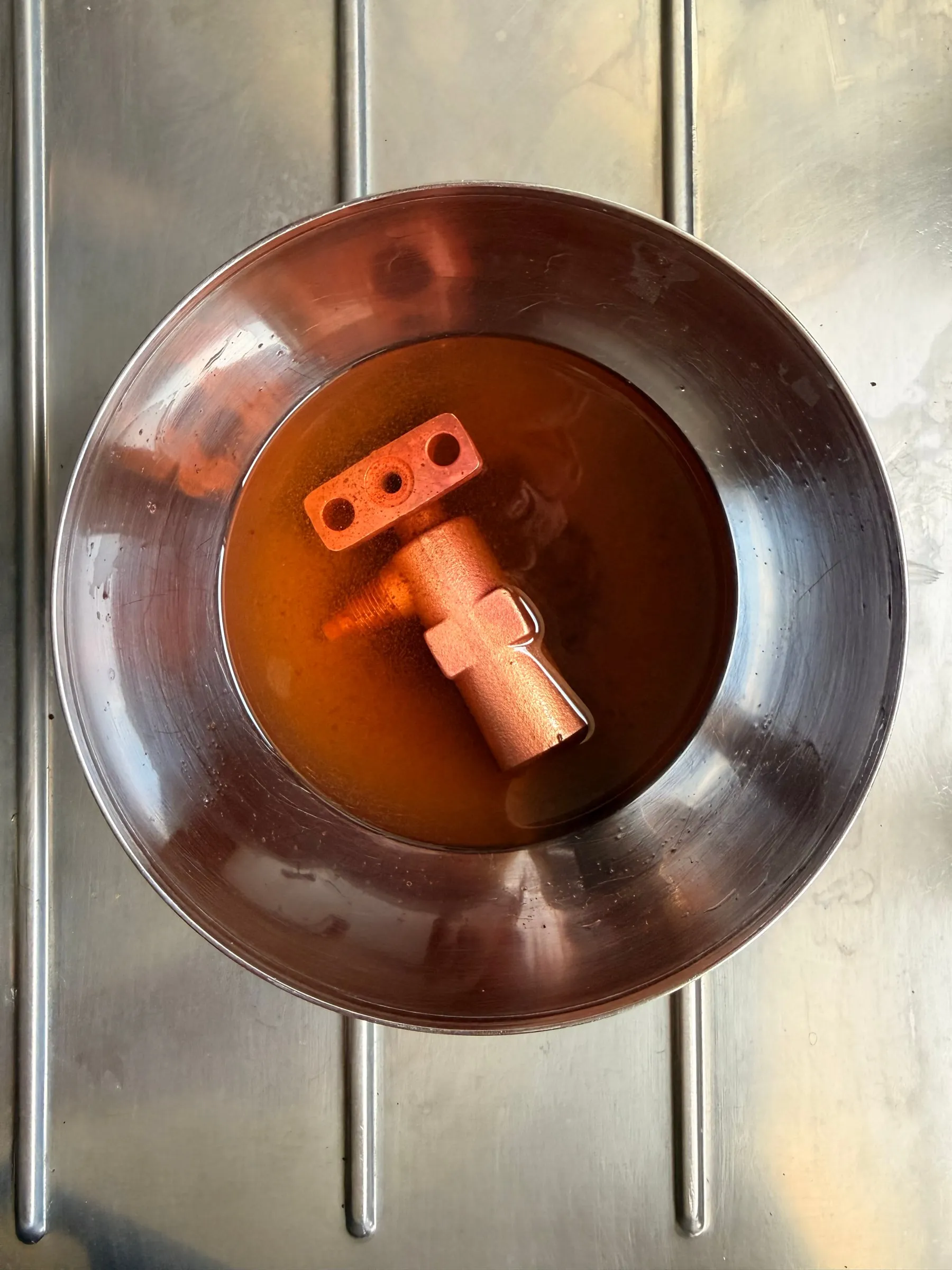
On the 21st the brass parts went into a bath of vinegar, salt and citric acid against the verdigris. No exact recipe: a couple of minutes at a time, out, a look at how much green had come off, back in, until it was gone, then a thorough rinse. The rock-hard green coating dissolves slowly.
7.Paint and the oven
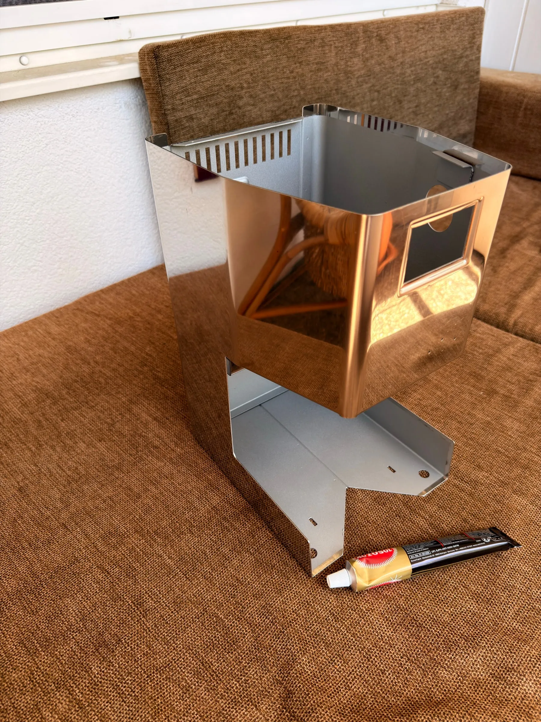
The 20th was paint day. The polished outer surfaces were masked with crepe tape and newspaper, then the inner steel frame surfaces sprayed with heat-resistant paint in aluminium silver, outdoors, in several thin coats: the last of three steps against the rust, after the converter and the polish. The masking took longer than the painting, and that is exactly why it looks good: no overspray on the polished steel.
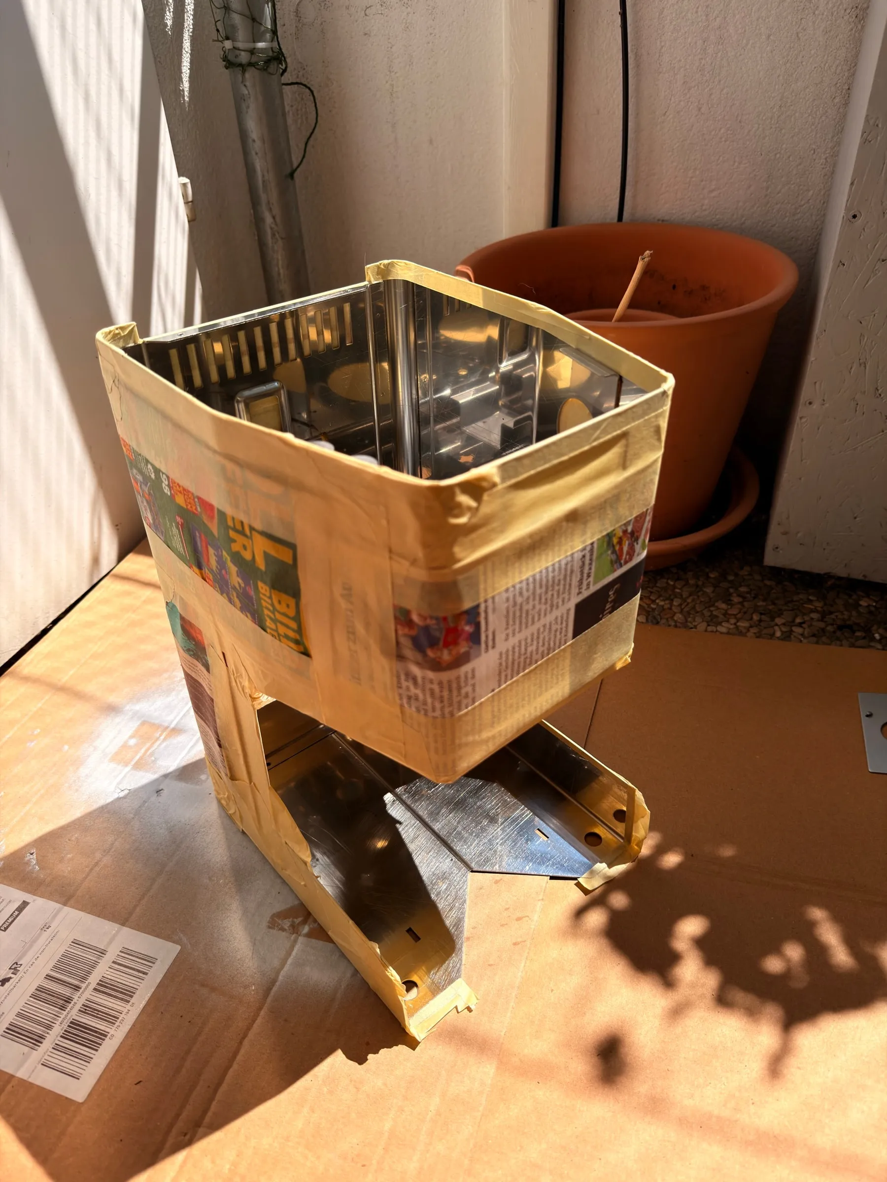
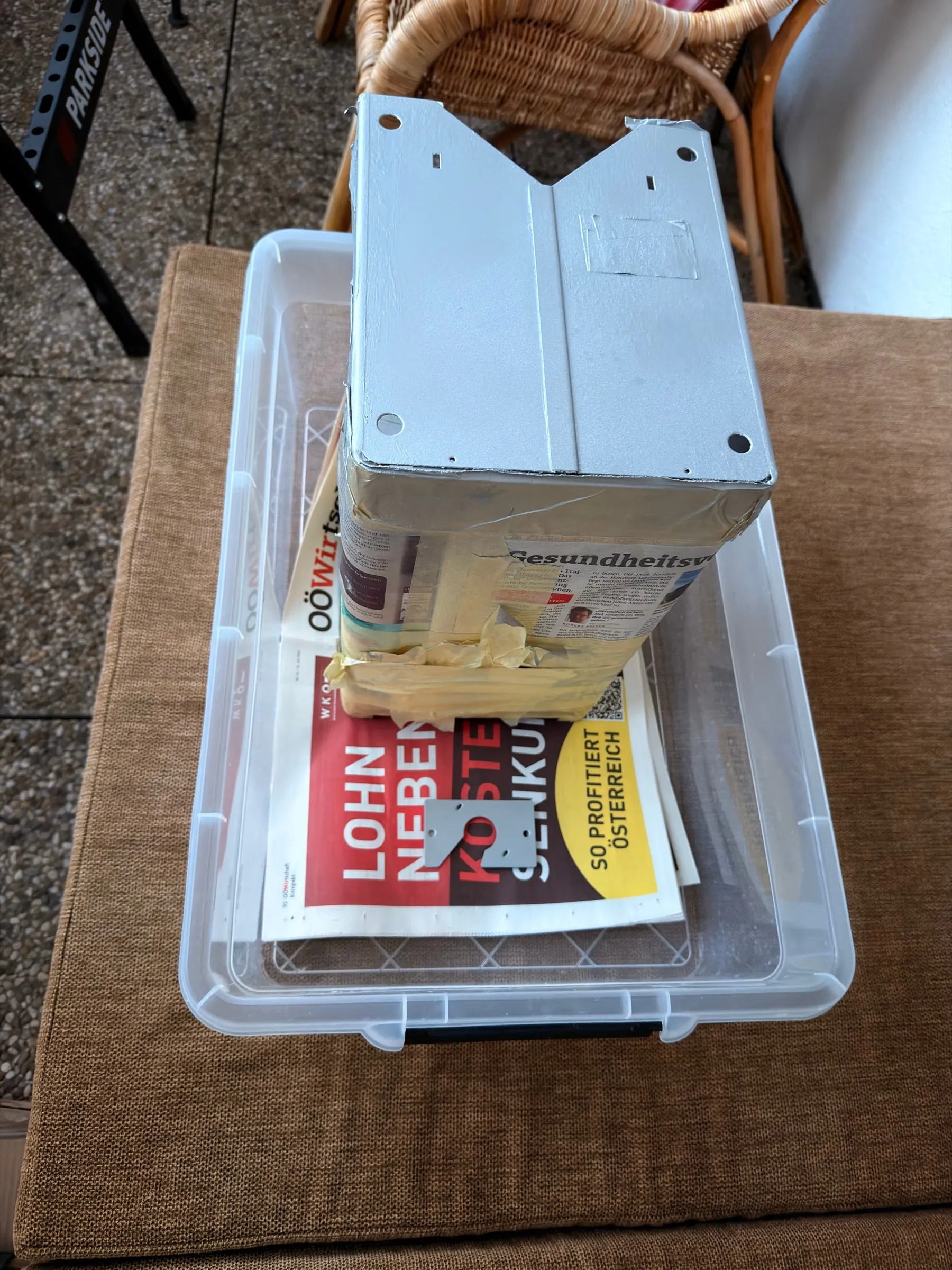
Silicone-resin heat paint stays soft when it only dries in air. The resin cross-links with heat, from about 150 °C and completing around 220 °C, and only then is it scratch- and chemical-resistant. So on 21 July the housing went into the kitchen oven at 220 °C for 30 minutes, the time on the spray can.
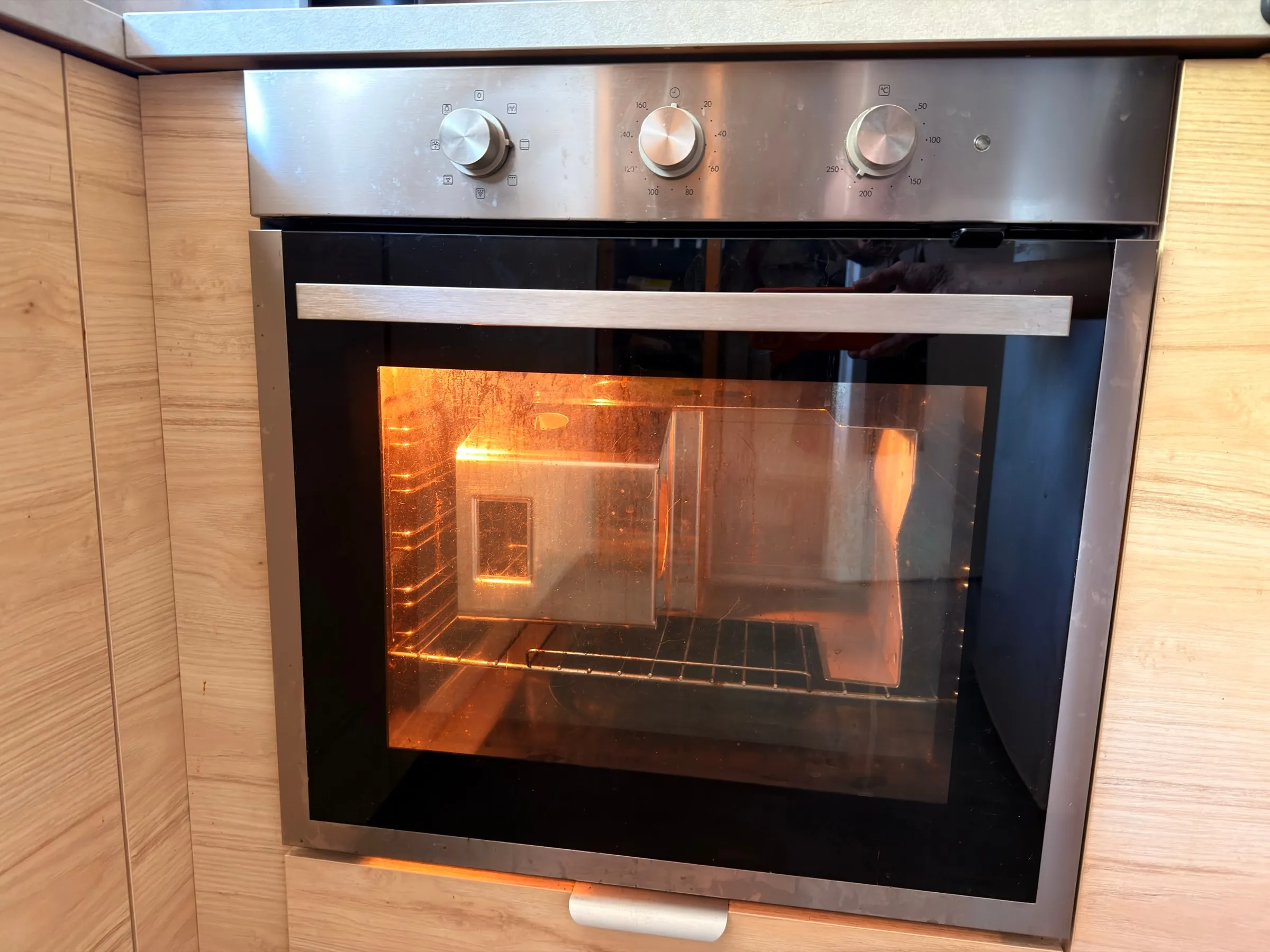
What worried me most were the tabs glued in on the 18th: two-part epoxy is rated to about 100 to 120 °C, well under the oven. They survived, and so, for the moment, did the factory-glued ones on the other side. The stainless housing is unbothered by 220 °C, temper colours only start around 300 °C, and the mirror finish came out unchanged. The only blemish was a small spot at the bottom corner where I had touched up the paint with solvent shortly before; the film was uneven there and blistered slightly. Cosmetic, underneath, barely visible.
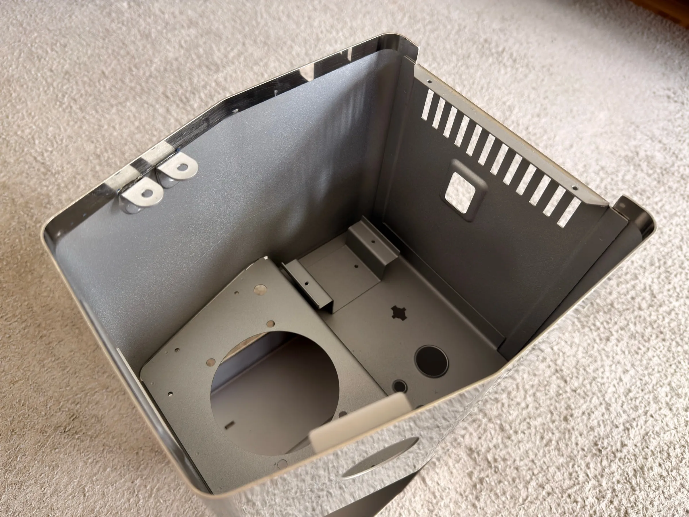
Fine work: the sealing face and the valve
8.Lapping and the over-pressure valve
Lapping the sealing face
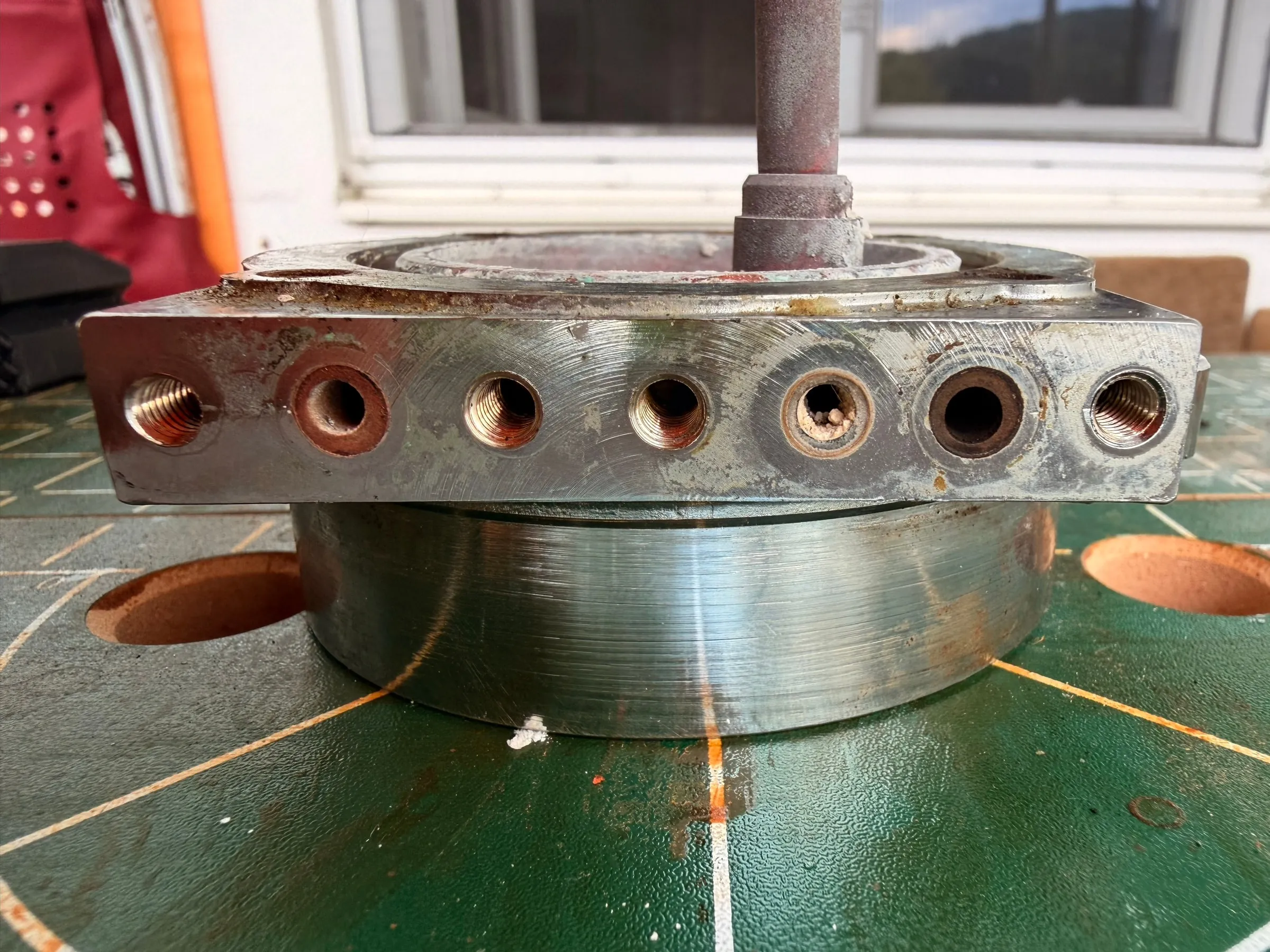
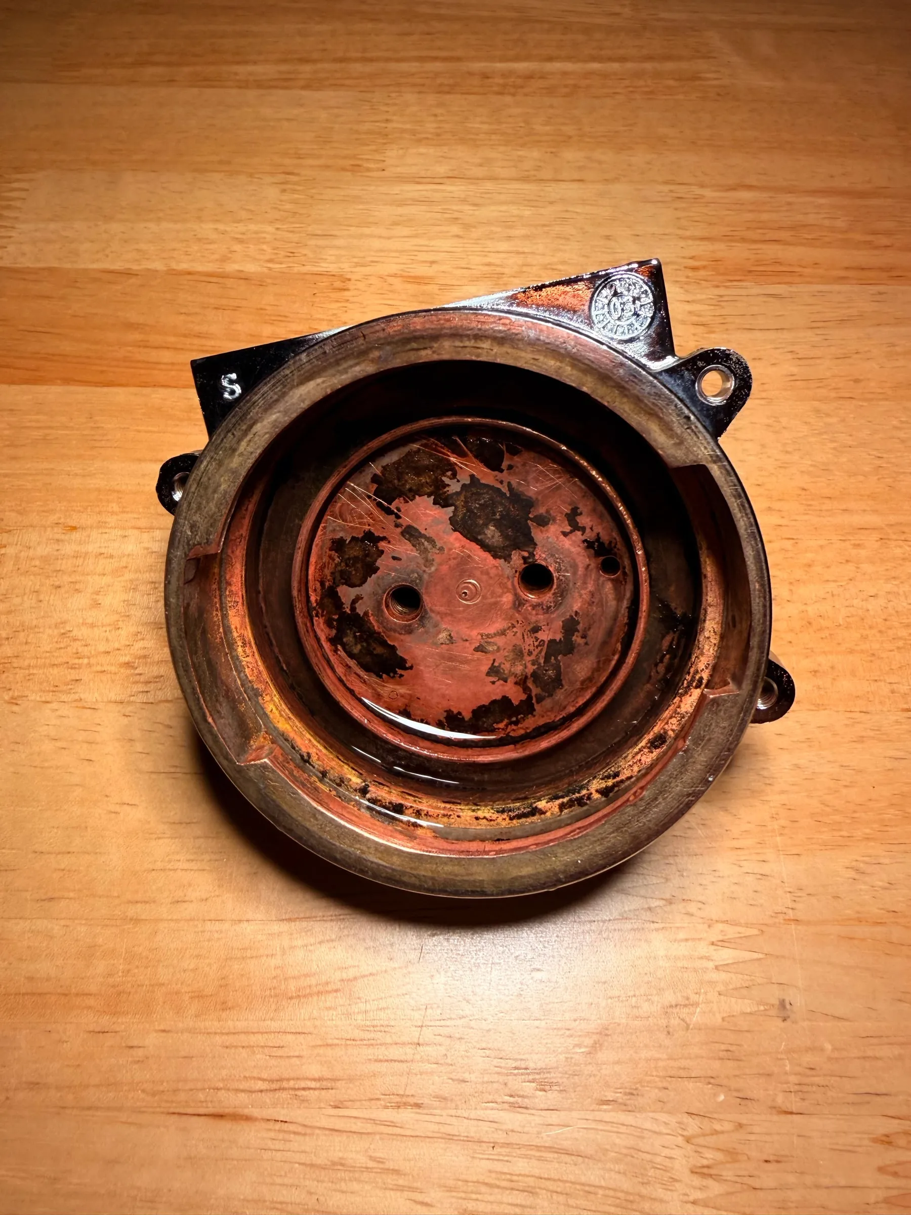
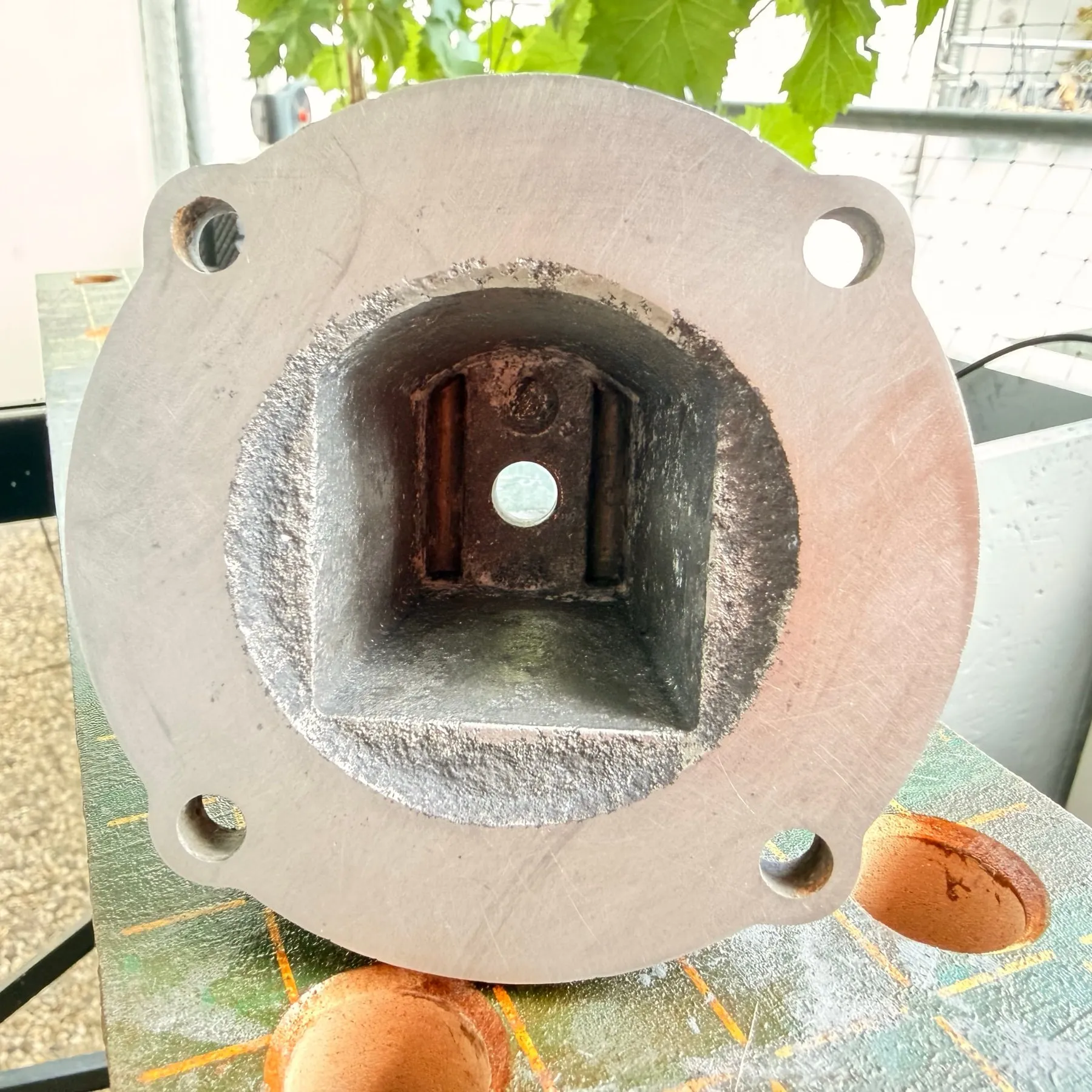
The afternoon of the 21st was fine work. The sealing face between boiler and brew group was lapped flat by wet sanding on silicon-carbide paper taped flat onto a board, the part drawn across it, 120, 180, 240 and 600 grit in turn. Sanding freehand rounds an edge; a sheet held flat keeps a face flat. The water side got another round of descaling.
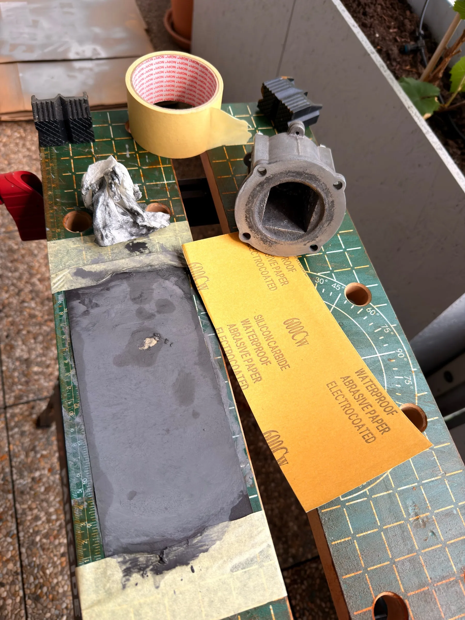
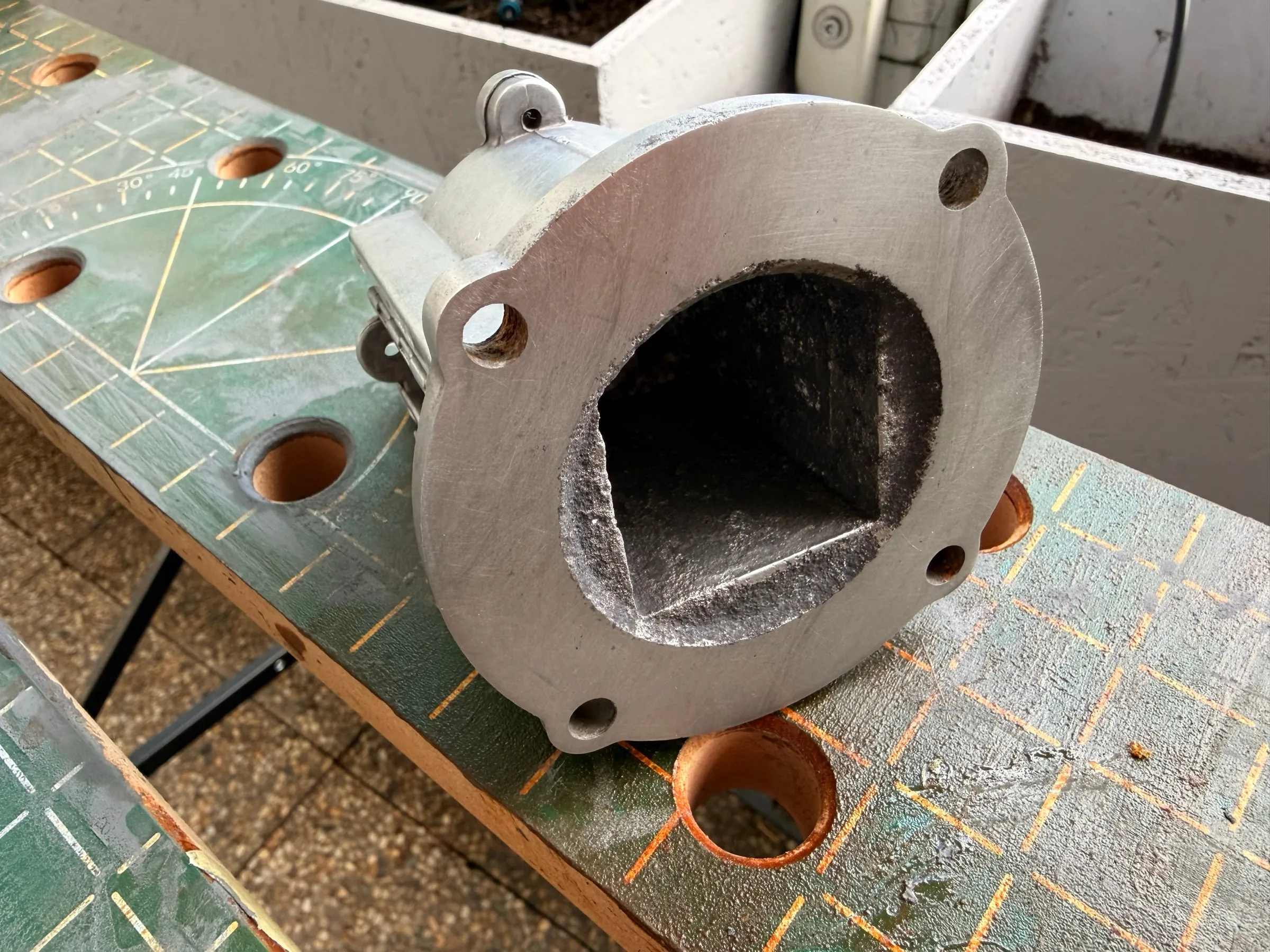
The same casting from the flange side, right after opening and after the descaling rounds and the lapping:
The over-pressure valve: fifteen turns
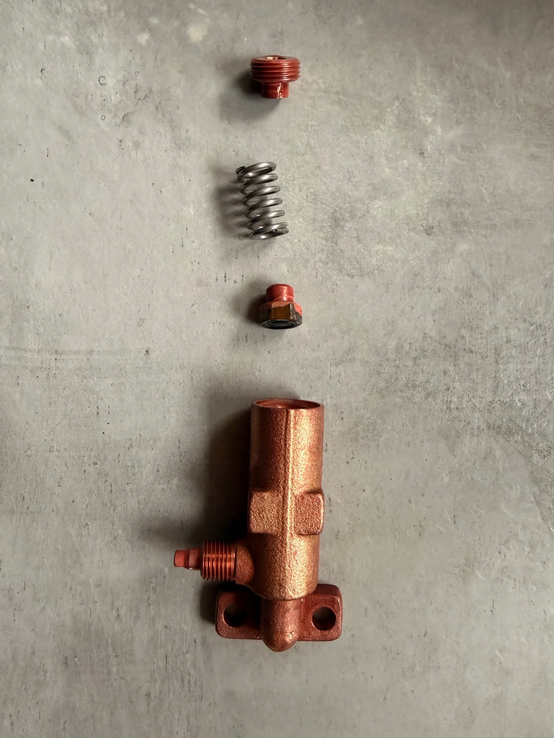
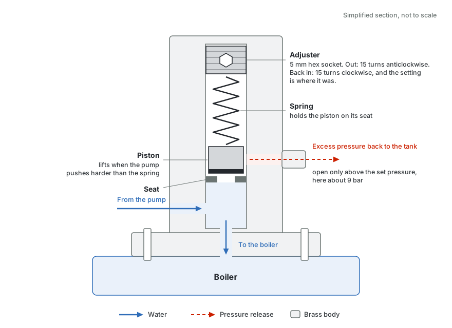
Then the over-pressure valve came apart completely, its adjuster stuck fast with deposits and verdigris. The most important number of the whole project:
How the over-pressure valve works, and why the number matters
The pump pushes against the piston from below; the spring holds the piston on its seat. Above the set pressure the piston lifts and the excess water goes back to the tank through the side port, so the brew group never sees more than the setting. The adjuster is nothing but the spring's stop: screw it in and the spring is stiffer, so the pressure rises; screw it out and it falls. Fifteen turns out and fifteen turns in puts the spring back to exactly the tension it had.
I could not find a precise drawing of this valve online, so this one was made for the project from the parts on the table.
Putting it back together
9.Reassembling the boiler
On 22 July the direction changed. Before that I had settled which joint gets which lubricant. Claude marked up a copy of the exploded drawing for me in three colours, green for food-grade silicone grease, blue for copper paste, red for dry, and that sheet lay on the table during the reassembly. The drawing is Gaggia's, so here is the same plan as a table, keyed to the position numbers of the official parts diagram ER0182:
| Position in ER0182 | Part | Treatment |
|---|---|---|
| 19 | The large O-ring between boiler and group body | Food-grade silicone grease, a thin film on the flanks |
| 8 | The O-ring between steam valve and boiler | Silicone grease, thin |
| 30 | The small O-rings at the solenoid valve flange | Silicone grease, thin |
| 41 | The O-rings of the same size at the steam pipe and, in the drawing, at the pump elbow | Silicone grease, thin (see the epilogue for the pump) |
| 28 | The over-pressure valve | Only its inner O-rings greased; seat, spring and adjuster stay dry |
| 21 | The group gasket | The thinnest film only |
| 6 | The boiler screws, M6 x 16 | Copper paste on the thread, nothing on the head |
| 22 and 24 | Shower holder plate and shower screen | Dry |
| Every flat pressed face | Flange faces, the lapped sealing face | Dry. No grease finds its way into the water path. |
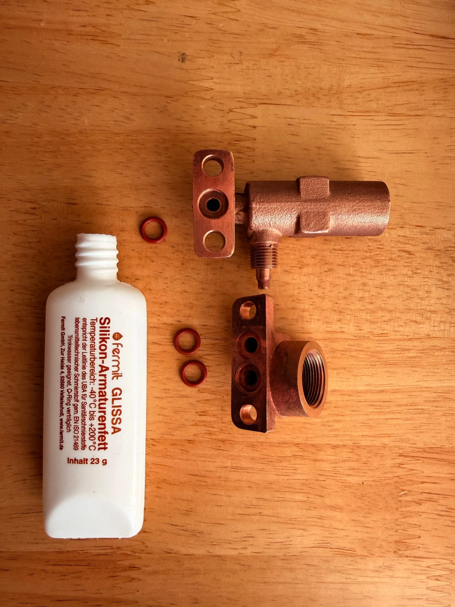
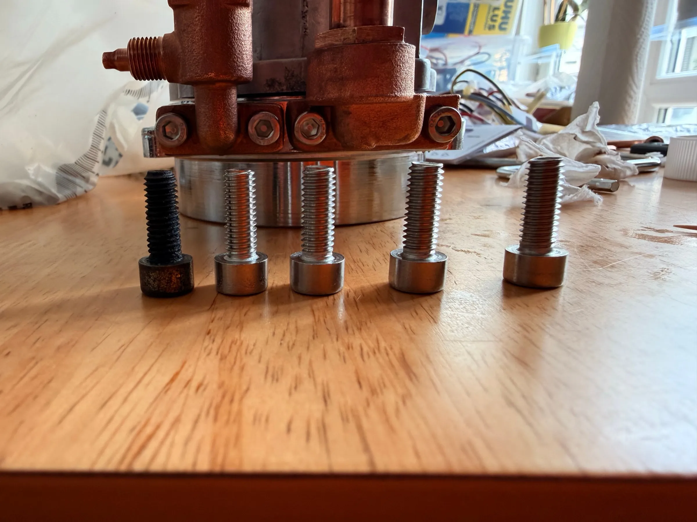
New gaskets and O-rings from the set, the big red boiler O-ring and the small red ones at the valve flanges, with a wafer-thin film of silicone grease on their flanks. The original boiler screws were retired: their threads had partly rusted, so the replacements are stainless A2 with copper paste on the thread, against rust and against the galvanic seizing that had made the old ones unremovable. Every other screw on the machine got the same treatment. Tightened crosswise and by feel: it is an aluminium thread, and copper paste lubricates, so less torque is needed than the old screws had suffered.
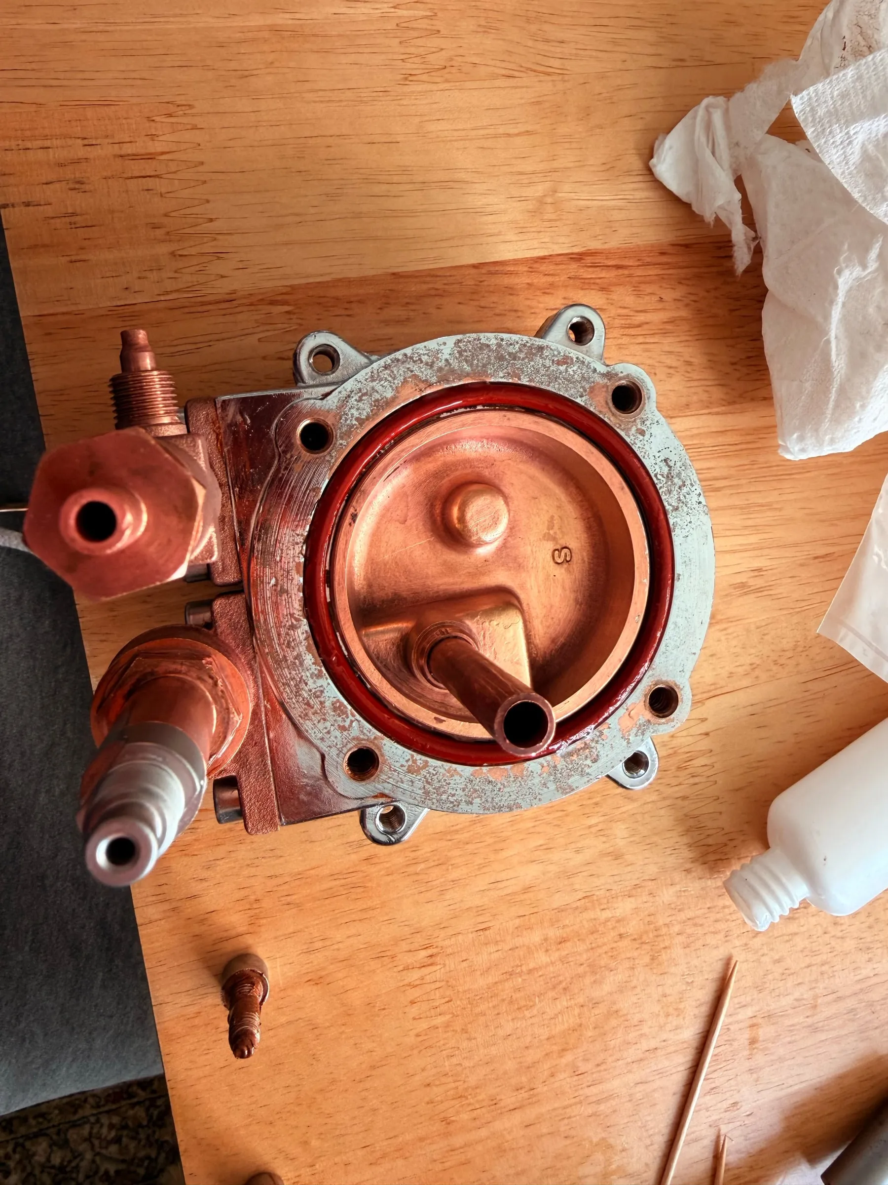
The brew group got a new shower screen and a new group gasket. The shower screen screw is small and strips easily: use a screwdriver that fits it exactly, and stop when it is snug.
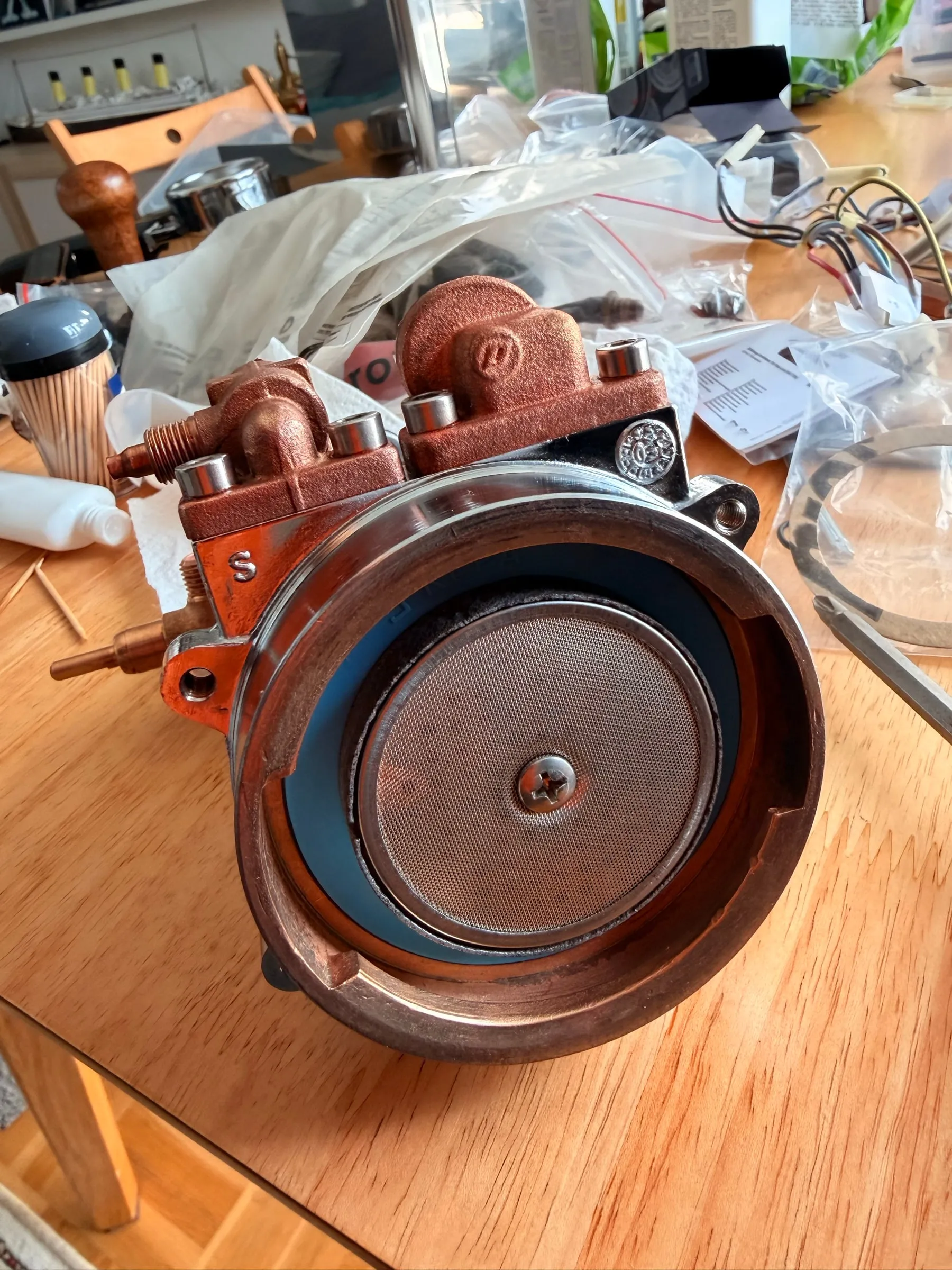
With the plan at hand, the reassembly was pleasantly unexciting.
10.Wiring and commissioning
Wiring, and tabs that came loose
The end of July was maintenance: a second polishing pass after baking, which made the mirror gloss final, and contact spray on every spade and switch contact.
On 1 August the wiring went in, cable by cable, label by label, earth first. The same day a late consequence of the oven showed up: not at the tabs I had glued in and worried about, which still hold, but at the factory-glued ones on the opposite side, which had let go days after the bake. Re-glued with the same epoxy, and no repeat to fear: in operation the frame only reaches 40 to 80 °C. Lesson: after thermal stress, check every bonded joint, not just the one you worried about.
Water first, then heat
On 29 August the machine stood there again, complete, nearly seven weeks after the purchase. The reflex is to switch it on and make coffee immediately. I knew better, because I had read up on it, but this is the point where a restoration can still go wrong.
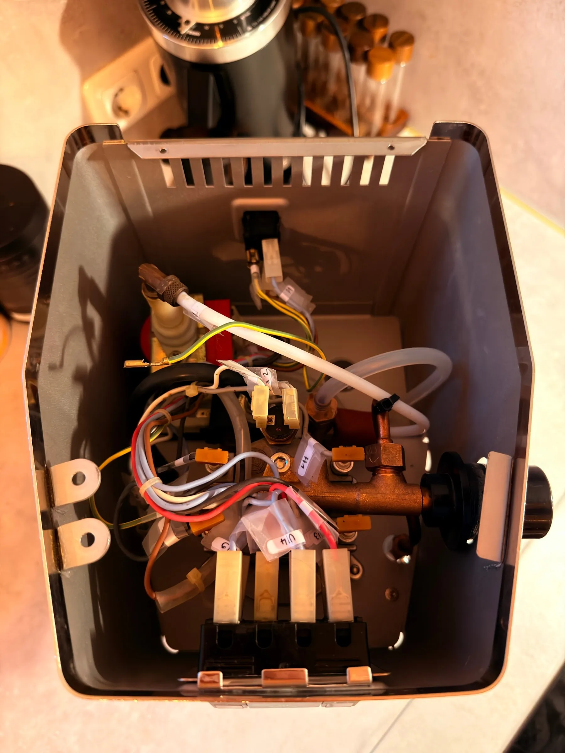
After a complete teardown the boiler is empty, and on a Classic the element heats as soon as the main switch is on. An empty boiler plus a live element costs you the element, or at least the thermal fuse. The original manual from 2004 says it in one sentence: filling the boiler with cold water makes the pump operational. So I read the manual instead of improvising, and wrote a checklist.
The commissioning routine, in the order I ran it:
- De-energised pre-check: every connection against the labels, earth continuity to the housing.
- Fill the boiler through the pump, cold.
- Air-bubble procedure through the steam wand if the pump does not prime by itself.
- Cold leak check with the housing open: pump running, every fitting watched.
- Flush two to three tank fillings before the first coffee.
- Hot pressure test with the blind filter.
- Re-check the boiler screws once the machine is cold again.
- Only then, the first shot.
The cold leak check earned its place: the brass pipe fittings at the three-way valve wept, not the flange screws but the fittings, which I had not tightened enough. I tightened them and then went over every fitting on the machine where a leak could occur.
The first shot
On 2 September, four days after the reassembly and after the routine above, the first test extraction ran: a steady, continuous stream into the cup, no stuttering, no dropout.
For nearly seven weeks this had been a heap of parts on a table. Of the roughly 50 hours, the biggest single item was the day with the seized boiler screws and the polishing.
Epilogue, two weeks later
11.A new pump and 8.5 bar
A new pump with a brass outlet
Two weeks after the first shot I swapped the pump anyway, not because the old Ulka EP5 had failed but because the EX5 has a brass outlet instead of a plastic one. Electrically and hydraulically the two are identical: 48 W, 230 V, a 1/8 inch outlet thread, a 6 mm inlet barb. The swap itself was quick, even the first time; the work was the question of how the one elbow fitting between pump and boiler seals.
The parts plan shows an O-ring there, but inside the new pump's outlet bore sits the check valve with its orange plastic cage, so there is no seat for an O-ring or a flat washer. The answer was two to three wraps of PTFE tape, wound in the screwing direction, the first turns left bare so nothing can fray off into the pressure side. That also explains why the old pump had no seal of any kind: its soft plastic outlet gives way a little under the brass elbow and seals itself, which a brass outlet cannot. Plastic forgives, brass does not, and that holds for every swap from an EP5 to an EX5.
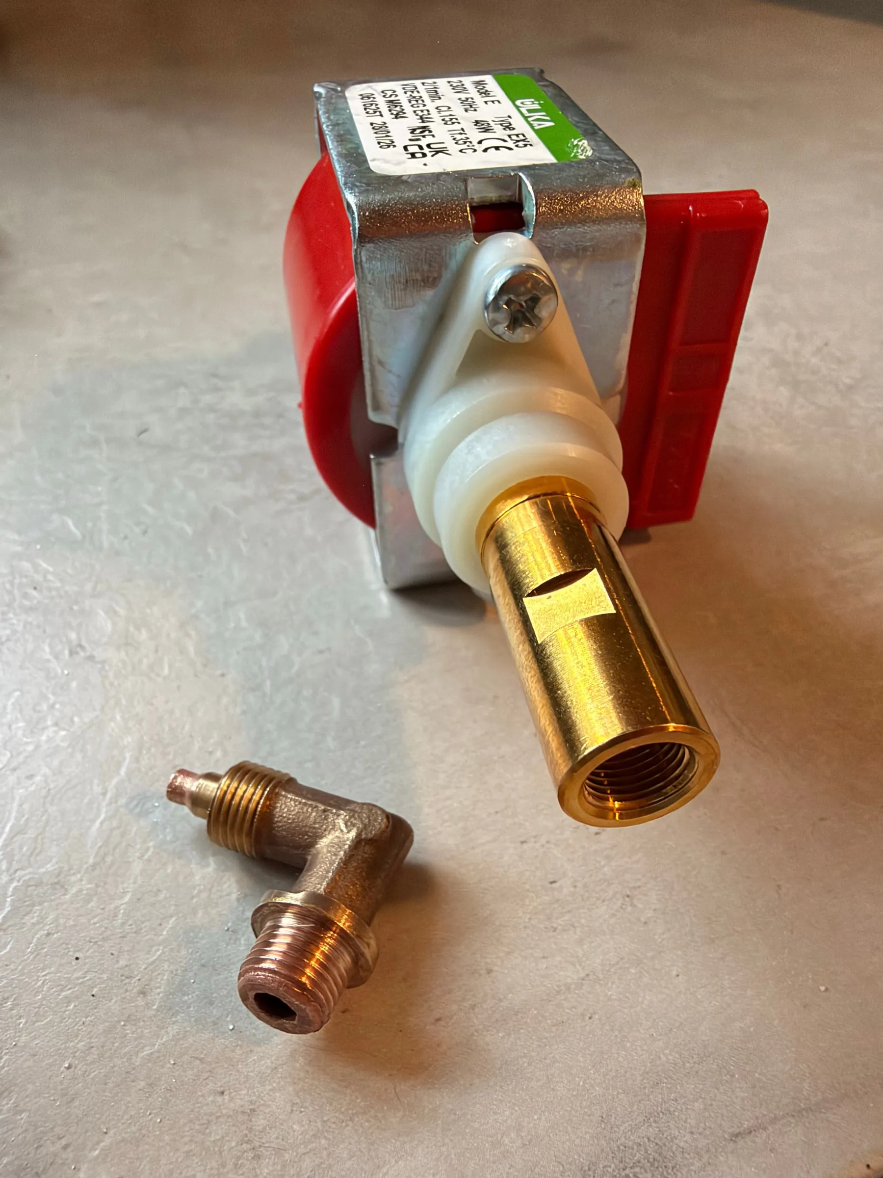
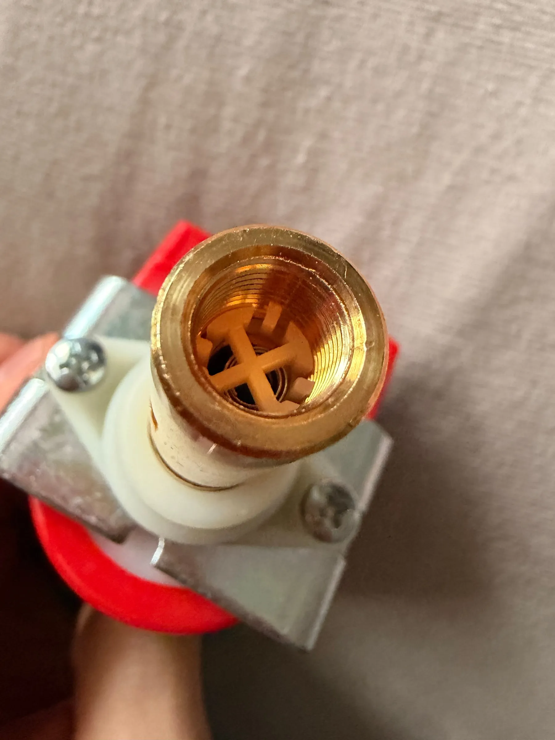
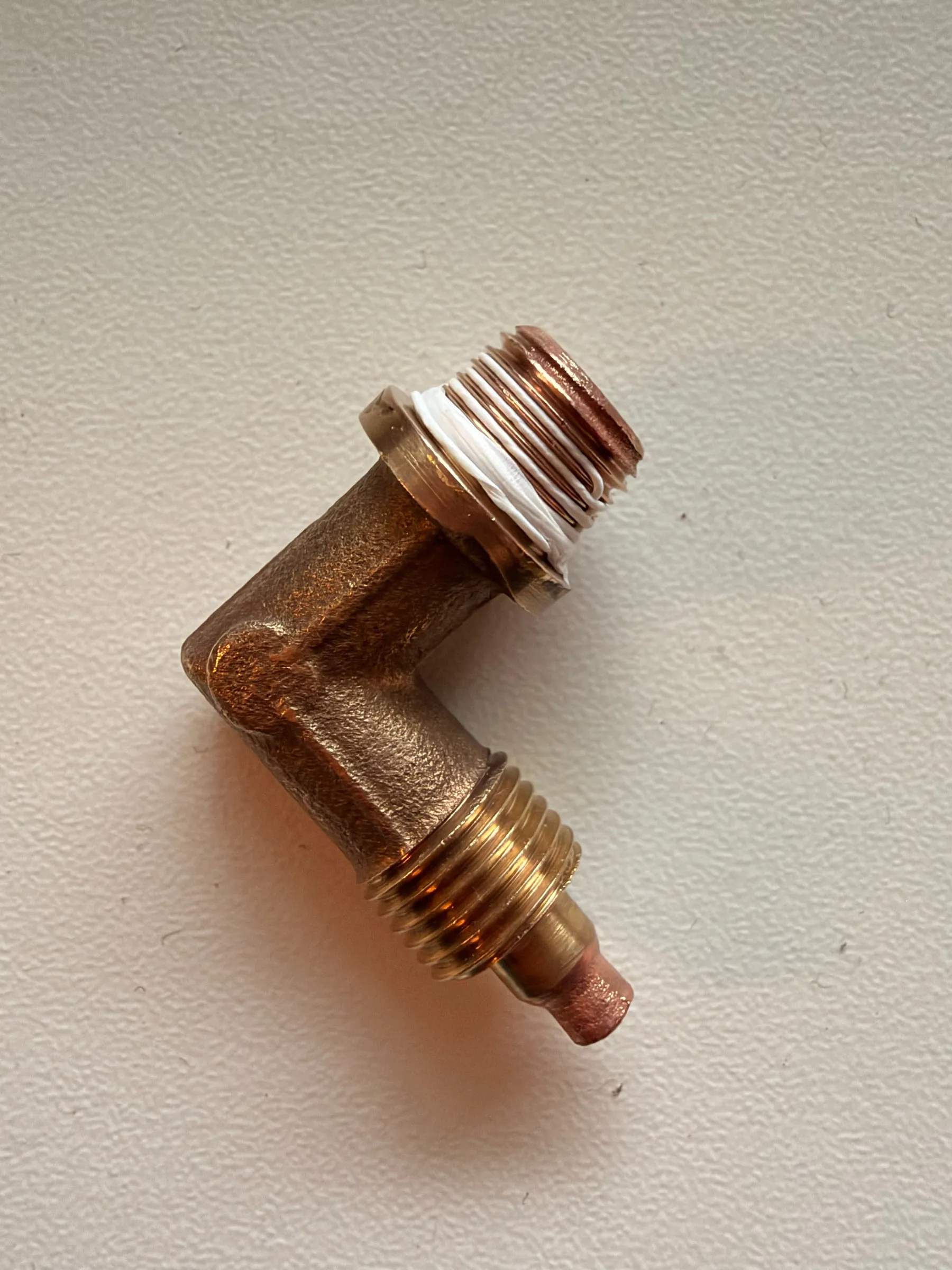
A parts plan shows a revision, not your machine: the drawing is from 2012, the machine from 2004. The part in your hand wins against any drawing.
A brass shower holder
One more part was swapped in the same round: the shower holder, the perforated plate behind the shower screen that spreads the water across it. The aluminium original was worn out, its coffee side covered in twenty years of baked-on residue, and it is no longer available from my parts supplier. The replacement is the same plate in brass. Stainless steel was the other option; I chose brass because it conducts heat better, which suits a group whose temperature a controller will hold in Part 2, and because it was the cheaper of the two.
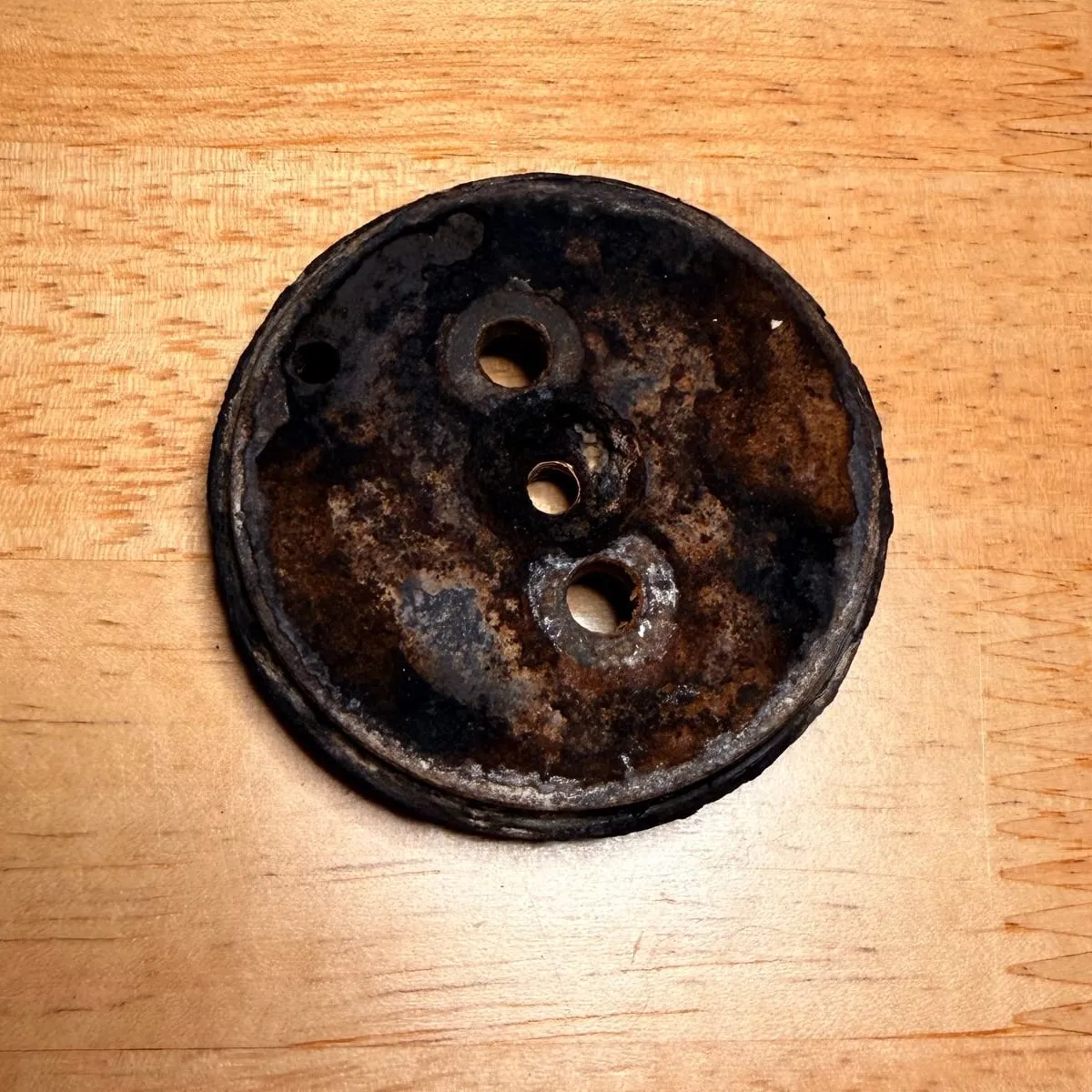
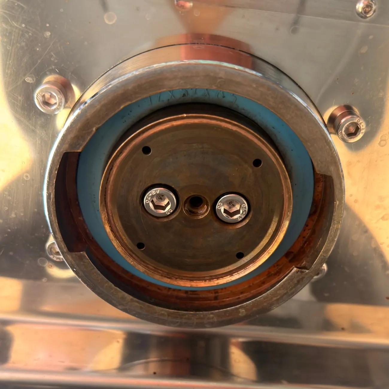
8.5 bar on the gauge
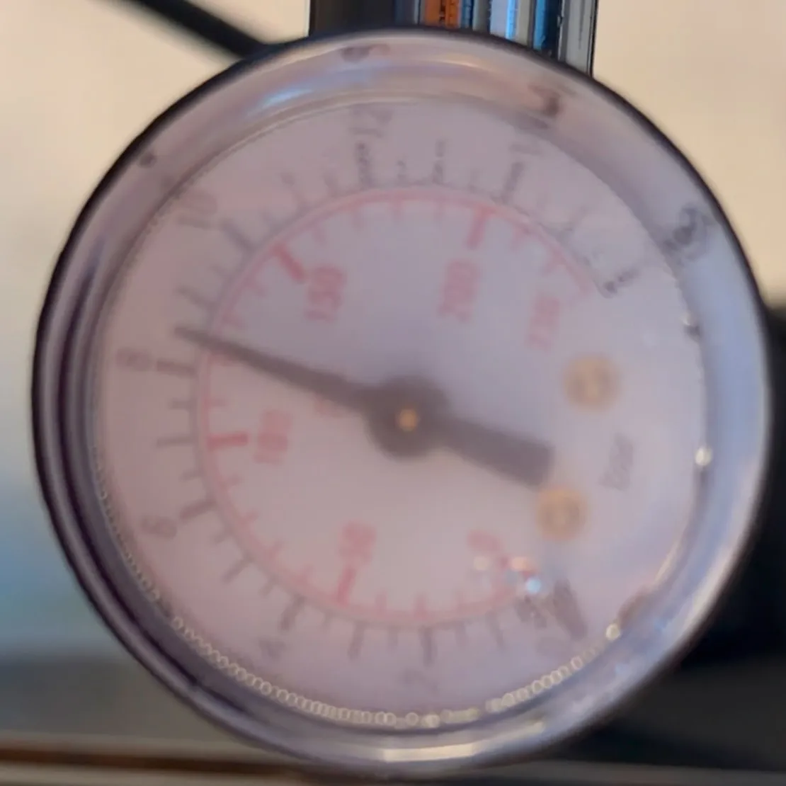
The evening test run was dry around the fitting, and the portafilter gauge showed 8.5 bar, in the ideal window around 9, without any readjustment. Fifteen turns out, fifteen turns in: the one number I wrote down during the teardown paid off in full.
What comes next
Mechanically the machine is done: sealed, descaled, rust-free, polished, running at the right pressure, and the espresso already tastes good. The blind filter and the Cafiza stay in use, because backflushing with them keeps the group and the solenoid valve clean, and the descaler comes out again at the next service. What the machine does not do yet is make the same espresso twice in a row: a 2004 bimetal thermostat swings several degrees around its set point, and the only way to hit a temperature is the old surfing trick with the steam switch.
Part 2 is the GaggiMate: an ESP32 controller with a PID loop, a proper temperature sensor and a display, replacing the thermostats that this restoration deliberately left alone. The electrical checks from 14 July were the groundwork for it.
Sources and further reading
None of this is original knowledge. These are the videos, threads and documents this project leaned on, roughly in the order they were needed.
Restoration videos (5)
- Restoring a 25-Year-Old 'Scrap' Gaggia Classic: Better Than New? by The Island Tech. A complete teardown, clean and rebuild of an early-2000s Classic bought as scrap, and the source of the 21 ohm reference value for the heating elements.
- Can You Flip a Broken Gaggia Classic? Full Restoration & Sale, also by The Island Tech. A leaking Classic Pro, diagnosed and repaired step by step.
- How To Clean and Rebuild a Gaggia Aluminum Boiler by Whole Latte Love. The reference for opening, descaling and resealing the boiler.
- Gaggia Classic Full Service and Descale, Boiler Strip, Seals by spidiq8. A full service with the boiler stripped and new seals.
- Gaggia Classic Restoration, a playlist by Luke Bennett that follows one machine from the first look at the sediment to the first espresso. Very good, and I kept coming back to it.
Diagnosis: heating element, insulation, solenoid (7)
- Home-Barista: Testing heating element with multimeter, the method and the V² / P formula.
- Coffee Forums UK: Gaggia Classic not heating up, typical element readings.
- CoffeeSnobs: Gaggia Classic, electrical issue, the earth fault test and the wiring.
- Home-Barista: How to test a Gaggia pump and solenoid valve?
- kaffee-netz: Gaggia Classic Diagnose Magnetventil (German), the listening test with the pump unplugged.
- KaffeeWiki: Magnetventil (German), acoustic, electrical and magnetic function tests.
- Whole Latte Love: Gaggia Classic Pro: Solenoid Valve Troubleshooting.
Teardown and official documents (4)
- iFixit: Gaggia Classic Espresso Machine, photo guides for the teardown and descaling.
- Gaggia North America: Gaggia Classic manuals, the original user manuals. The commissioning rule quoted above comes from the 2004 manual.
- The official parts diagram ER0182 and the wiring diagram (120 V version, same topology as the 230 V machine), hosted by Whole Latte Love. The position numbers in the lubrication table above refer to this drawing.
- Moja Gaggia, Moje Mody (Polish), a collection of Gaggia schematics, wiring diagrams and manuals.
Parts catalogues with drawings (3)
- espressoXXL, where the maintenance set and the baskets came from.
- Avola Coffeesystems, the complete component list for the Classic with part numbers, and the source of the pump, the shower holder and the gauge.
- gastrotiger.at, part search with drawings.
For Part 2 (1)
Working with Claude
One more thing belongs in an honest account: I did not do this alone. Claude, Anthropic's AI assistant, was part of the project from the first evening, and it has changed the way I work on something like this.
Concretely, it boiled three long restoration videos down into one ordered to-do list for my machine, translated the US products in them into things I can buy in Austria, and split the shopping list by shop. It kept the project notes up to date after every session; this article is written from those notes. Where I could not find a precise reference, it made one: the water-path diagram near the top, the section of the over-pressure valve, and the lubrication plan, the official exploded drawing marked up with the O-rings, screws and dry faces in three colours, which I used during reassembly and which appears above as a table. And it answered the many small questions that come up with a part in your hand: how much heat a two-part epoxy survives, at what temperature the paint cures, whether a thread is parallel or tapered, how a pump fitting seals when the drawing and the part disagree. That saved a lot of searching through forums and manuals.
It is an assistant, not an authority. The solenoid valve is the example: the confident audio analysis that called the valve healthy came from the same assistant, and it was wrong. Measuring, a second look and your own ears still count.